Chapter 3 - Installing Instrument Boards
59
Setting the GTXI-702 Carrier Board I/O Address
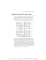
The GTXI-702 utilizes address lines A11-A15 for offset and A8 for
additional decoding. Address lines A8 and A11 can be disabled in
carrier addressing (default).
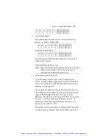
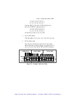
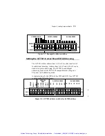
Table 3-4 shows the switch layout with an example at offset address
2000H.
A15 A14 A13 A12 A11 A11
EN
A8
EN
A8
On
On
On
On
On
On
On
Off
Table 3-4: Carrier Board Offset Switches
These switches are identified as described in Table 3-5:
SW1-1
to 4
A15-
A12
Offset value by increments of 1000h. ‘Off’
position is ‘1’ and ‘On’ position is ‘0’.
SW1-5 A11
Offset value by increments of 0800h. A11EN
must be in ‘Off’ position to enable this offsetting.
SW1-6,7 A8EN,
A11EN
When these switches are in ‘Off’ position, A8
and A11are enabled. When in ‘On’ position, the
carrier board’s offset switch settings are
compatible with older versions of the carrier.
SW1-8 A8
This switch allows two carrier boards to be used
with the same offset configuration. The switch
can be used if one carrier holds a board using I/O
space in the range of 200h-2FFh (switch is ‘On’)
while the other carrier holds a board in the
address range of 300h-3FFh (switch is ‘Off’).
Table 3-5: GTXI-702 Switches Assignments
Artisan Technology Group - Quality Instrumentation ... Guaranteed | (888) 88-SOURCE | www.artisantg.com


