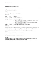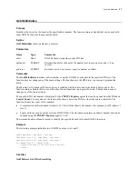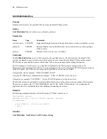
27
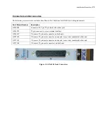
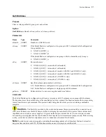
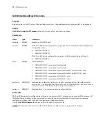
J6 Connector
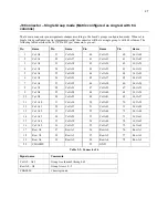
– Single Group mode (Matrix configured as single A with 64
columns)
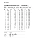
The J6 main connector pin assignments changes according to the board’s groups configuration mode. When set to
Single Group configuration (set programmatically) the connector will have a single group A with 64 columns. The
following table describes the J6 (78 Pin D Type) connector’s pin out:
Pin
Name
Pin
Name
Pin
Name
Pin
Name
1
Col A0
21
Col A16
40
Col A32
60
Col A48
2
Col A1
22
Col A17
41
Col A33
61
Col A49
3
Col A2
23
Col A18
42
Col A34
62
Col A50
4
Col A3
24
Col A19
43
Col A35
63
Col A51
5
Col A4
25
Col A20
44
Col A36
64
Col A52
6
Col A5
26
Col A21
45
Col A37
65
Col A53
7
Col A6
27
Col A22
46
Col A38
66
Col A54
8
Col A7
28
Col A23
47
Col A39
67
Col A55
9
Col A8
29
Col A24
48
Col A40
68
Col A56
10
Col A9
30
Col A25
49
Col A41
69
Col A57
11
Col A10
31
Col A26
50
Col A42
70
Col A58
12
Col A11
32
Col A27
51
Col A43
71
Col A59
13
Col A12
33
Col A28
52
Col A44
72
Col A60
14
Col A13
34
Col A29
53
Col A45
73
Col A61
15
Col A14
35
Col A30
54
Col A46
74
Col A62
16
Col A15
36
Col A31
55
Col A47
75
Col A63
17
Row A0
37
Row A1
56
Row A0
76
Row A1
18
Row A2
38
Row A3
57
Row A2
77
Row A3
19
Row A4
39
Row A5
58
Row A4
78
Row A5
20
CHASSIS
59
GND
Table 3-2: Connector J6
Signal name
Comments
Col A0 – A63
Group A columns 0 through 63
Row A0 – A5
Group A rows 0 - 5
CHASSIS
Chassis ground
Summary of Contents for GX6384-1
Page 2: ......
Page 7: ...GX6384 User s Guide v Index 55 ...
Page 8: ...vi GX6384 User s Guide ...
Page 36: ...28 GX6384 User s Guide ...

