Page 19
mPower 300 Series (Rev G)
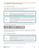
The brass screw next to the AC connector is a central grounding point for internal use! Do not un-
screw to connect external GND potential here! The unit is grounded via the AC cable.
4.5 Remote Sensing Connection
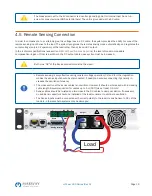
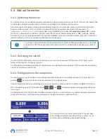
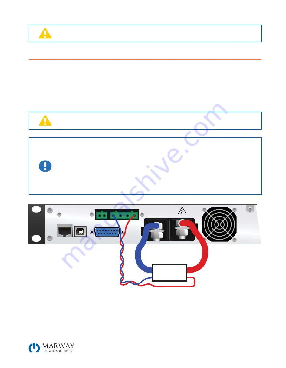
In order to compensate, to a certain degree, the voltage loss in a DC cable, the system provides the ability to connect the
remote sensing input Sense to the load. The system recognizes the remote sensing mode automatically, and regulates the
output voltage (only in CV operation) at the load rather than at its own DC output.
In the technical specifications (see section
8. Model Specifications Appendix
) the level of maximum possible
compensation is given. If that is insufficient, the DC output cable cross section must be increased.
Both pins “NC” of the Sense connector must not be wired!
•
Remote sensing is only effective during constant voltage operation (CV) and for other regulation
modes the sense input should be disconnected, if possible, because connecting it generally in-
creases the oscillation tendency
•
The cross section of the sense cables is noncritical. However, it should be increased with increasing
cable length. Recommendation: for cables up to 5 m (16 ft) use at least 0.5 mm²
•
Sense cables should be twisted and laid close to the DC cables to damp oscillation. If necessary,
an additional capacitor should be installed at the load/consumer to eliminate oscillation
•
The Sense inputs must be connected with correct polarity to the load, means Sense+ to DC+ of the
load etc., otherwise both systems may be damaged
Share
Sense
NC NC
+ -
-
+
Analog Interface
USB
LAN
Output
Load


