background image

Page 8

Optima 829 Series

3  Operation

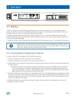
Ethernet Serial

Aux 1

Aux 2

Ethernet Serial

Aux 1

Aux 2

Values

Devices

Menu

Optima RCM

OFF

ON

OFF

ON

CB X

CB X

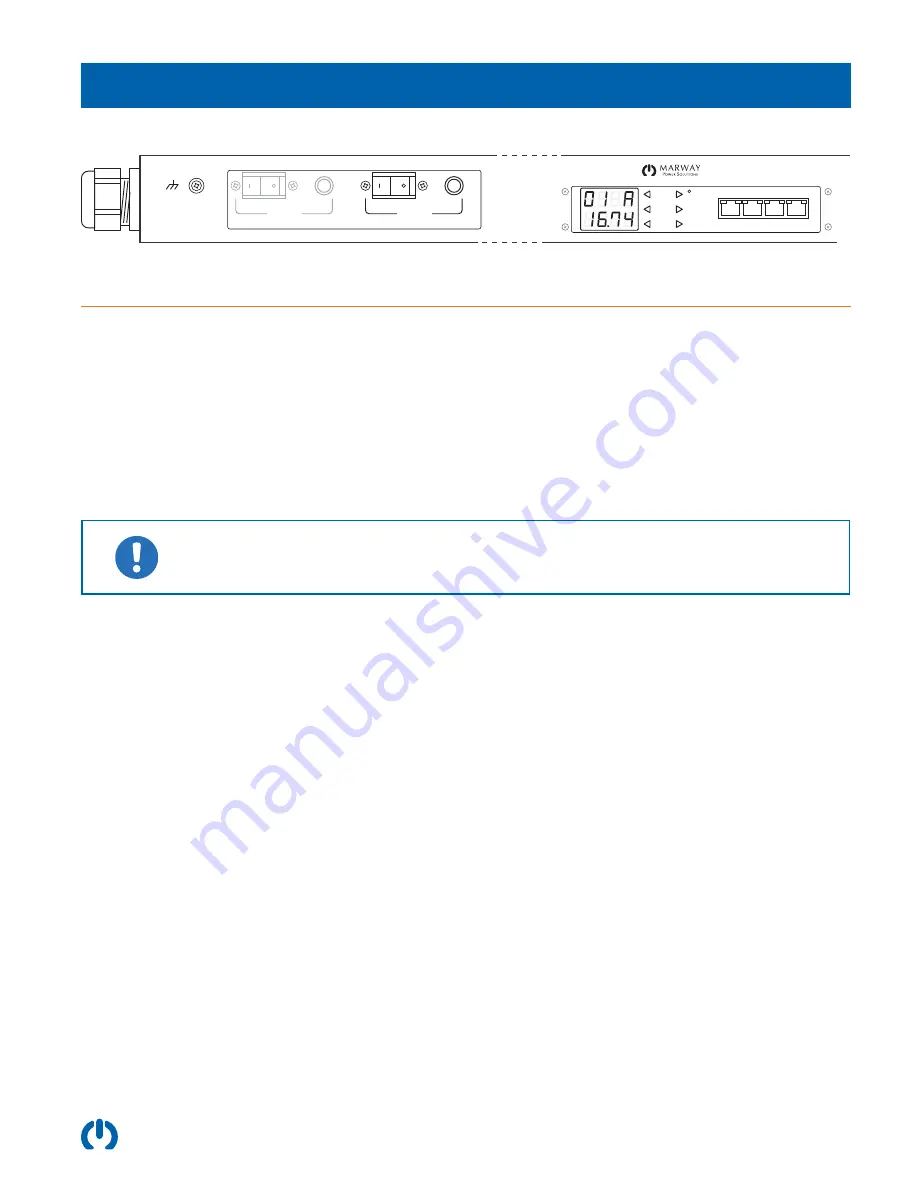
Your model may have 1 or 2 branch breakers.

Your model may or may not have a power meter.

3.1  Startup

In order to monitor or control the system over Ethernet, it will need to be configured to run on your specific network. 

However, to perform an electrical or installation validation test, or even to run the system indefinitely without the use of 

the network, the unit can be run without first configuring the software.
By default, the system will enable all outlets, though it may take a minute or so before outlets are switched on after 

power is applied. This delay is caused by the software system starting up, and eventually setting the state of each relay 

according to configurable settings.
In the sections below, a startup process is described suitable for first-time network setup, or running without the software.

The breaker(s) can be used to manually cut power from the outlets. However, even with the circuit 

breaker(s) Off, as soon as the inlet of the PDU is plugged into a live facility outlet, the control system 

of the PDU is powered, and the software will start running.

3.1.1  Startup Without Configuring the Software

It is assumed the PDU is not plugged into the facility power source.
1.  Switch all breakers on the PDU control panel to the Off position. 
2.  If there is a facility disconnect switch for the PDU inlet, switch that Off.
3.  Insert the PDU’s inlet connector into the facility mains power source. If there is a facility power disconnect, switch that 

to the On position.

7.1. At this point, the PDU control system is energized. Outlets will not have power, because the PDU’s breaker(s) 

are off, but the software will begin its startup process. The default factory setting configures the software to 

switch the outlet relays on, however, while the breaker(s) are off, power is not actually delivered to the outlets. 

Allow about a minute for the software to switch on the relays.

4.  Switch the breaker(s) to the On position, and the indicator(s) will be lit. This indicator does not necessarily mean power 

is applied to the outlets. It simply means the breaker is on and power is 

available

 to that branch’s outlets. The internal 

outlet control relays are able to prevent power from reaching the outlets. However, with a factory default setup, power 

should now be applied to all outlets.

The PDU can continue to be used in this way as long as needed. The software can be configured later, or can be left 

unconfigured if it will not be used.

Summary of Contents for Optima 829 Series

Page 1: ...ma RCM J 17 J 18 J 19 J 20 J 21 J 22 J 23 J 24 J 9 J 10 J 11 J 12 J 13 J 14 J 15 J 16 J 1 J 2 J 3 J 4 J 5 J 6 J 7 J 8 Ethernet Serial Aux 1 Aux 2 Ethernet Serial Aux 1 Aux 2 Values Devices Menu CB 3 CB 2 CB 1 CB 1 OFF ON Optima RCM Ethernet Serial Aux 1 Aux 2 Ethernet Serial Aux 1 Aux 2 Values Devices Menu J 1 J 2 J 3 J 4 J 5 J 6 J 7 J 8 J 9 J 10 J 11 J 12 J 13 J 14 J 15 J 16 CB 1 CB 1 CB 1 OFF ON...

Page 2: ...curité FR 4 1 5 General Description 5 1 6 Product Models 5 1 7 Product Ratings 6 2 Installation 7 2 1 Installation Notes 7 3 Operation 8 3 1 Startup 8 3 1 1 Startup Without Configuring the Software 8 3 1 2 Startup to Configure the Software 9 3 2 Ethernet and Serial Control 9 3 3 Breakers 9 3 4 Digital Power Meter Option 9 4 Specifications 10 ...

Page 3: ... signal cabling Do not open this product as it contains no user serviceable parts inside All service concerns should be directed to Marway Power Solutions If this product is used in a manner which does not comply with this instruction manual the protection provided by the equipment may be impaired All work on connections must be carried out under zero voltage output disconnect and may only be perf...

Page 4: ...s ce produit car il ne contient aucune pièce réparable par l utilisateur Tous les problèmes de service doivent être adressés à Marway Power Solutions Si ce produit est utilisé d une manière non conforme au présent manuel d instructions la protection fournie par l équipement peut être compromise Tous les travaux sur les connexions doivent être effectués sous une tension nulle et ne doivent être eff...

Page 5: ... primarily organized by size full height and short height then by the outlet configurations Marway s Standard Products Catalog includes more detailed tables with exact model number configurations with inlets outlets and options identified Chassis Style Model RCM Type Inlet Configuration Outlet Configuration IEC C13 IEC C19 NEMA 5 15R NEMA 5 20R Full Height 72 IEC 829001 PSW NSW C20 chassis 36 6 82...

Page 6: ...9004 829012 200 240 Vac 1ɸ 50 60 Hz 24 A continuous 30 A maximum 200 240 Vac 1ɸ 12 A continuous 16 A max per C13 receptacle 200 240 Vac 1ɸ 16 A continuous 20 A max per C19 receptacle 16 A continuous 20 A max total per outlet group regardless of receptacle count used 24 A continuous 30 A max total per unit regardless of receptacle count used 829005 829013 100 120 Vac 1ɸ 50 60 Hz 12 A continuous 15 ...

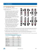
Page 7: ...e chassis includes a redundant chassis ground screw and ground wire If desired for your installation location connect the chassis ground wire to the rack cabinet using an appropriate fastener 4 Optionally connect the appropriate cables between the PDU outlets and the equipment being powered by the PDU This may be done later according to the startup procedures suitable to the end user s equipment a...

Page 8: ...and the software will start running 3 1 1 Startup Without Configuring the Software It is assumed the PDU is not plugged into the facility power source 1 Switch all breakers on the PDU control panel to the Off position 2 If there is a facility disconnect switch for the PDU inlet switch that Off 3 Insert the PDU s inlet connector into the facility mains power source If there is a facility power disc...

Page 9: ... computer to the Serial port Marway offers these cables as part number 311118 000 They can also be found on many online cable retailer web sites 3 3 Breakers Various models have one or two breakers When there is a single breaker in effect this behaves like a main breaker protecting the whole unit and providing on off control for the whole unit When there are two breakers each breaker protects one ...

Page 10: ... 120 Vac models have a single pulse energy rating of 100 joules 240 Vac models have a single pulse energy rating of 170 joules All models have a peak surge current rating of 10 000 A for a single pulse 8x20µs wave Environment Operating Temperature 32 F to 122 F Maximum Altitude 6 562 feet Relative Humidity 5 to 85 non condensing Networking Ethernet 10 100T IPv4 DHCP Static Web Interface HTTP HTTPS...

Page 11: ...DC are trademarks of Marway Power Systems Inc All other trademarks are the property of their respective owners Global Support Contacts Web www marway com Email support marway com sales marway com Phone 800 462 7929 7am 5pm PST There may be updates to this documentation at http www marway com docs Marway Power Solutions 1721 S Grand Ave Santa Ana CA 92705 800 462 7929 marway marway com ...

Reviews: