Page 15
Optima 820 Series
5
Specifications
Networking
Ethernet 10/100T
•
IPv4: DHCP, Static
Web Interface
•
HTTP, HTTPS
Command Line Interface
•
Telnet, SSH, RS-232
SNMP
•
v2/v3
•
Access to power data, alarms,
outlet switching
Alerts
• Email over SMTP
• SMS over SMTP
•
SNMP v2/v3 Traps
Scriptability
• RESTful API
•
Telnet/SSH
• SNMP
Other Protocols
•
SNTP, SNMP, FTP
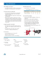
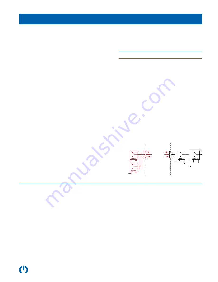
Remote EPO (standard)
•
Panel connector: AMP #1-480304-0, 250 Vac, 4 A
maximum.
•
Mating cable connector: AMP #1-480305-0.
•
Connectors J20, J21, J22 are wired in parallel.
•
Connector J23 has the delayed enable signal.
•
All outlets except the two utility outlets (J16/J17
on some models, J17/J18 on other models) are
managed by the Remote Control Bus.
•
The utility outlets are always powered relative to the
Main Breaker state.
Pin 3 : Return
Power On
Power Off,
EPO Active
Pin 2 : Disable
Pin 1 : Enable
J1
Marway UCP, or
customer supplied circuit
Remote On
EPO Override
Enable Outlet
Groups B & C
Marway Optima PDU
Optima Remote EPO Circuit
Inlet Voltage and Current
•
All models 120/208 Vac, 50/60 Hz, three-phase wye
•
All models 24 A continuous load / 30 A maximum
Overload Protection (standard)
•
All models include a four-pole main circuit breaker
wired with all three phases and neutral passing
through the breaker.
•
All branch breakers are UL 489, 16 A continuous load
(20 A maximum)
•
Based on NEC regulations, traditional load ratings
are de-rated to 80% for continuous duty. For example,
a traditional 30 A maximum rating is now interpreted
and labeled as a 24 A continuous duty rating. Optima
current ratings are shown with continuous/maximum
rating values.
Surge Suppression (standard)
•
All models include a thermally protected varistor on
each phase with a single-pulse energy rating of 120
joules.
•
All models have a peak surge current rating of
10,000 A for a single pulse 8x20µs wave.
Environment
•
Operating Temperature: 32°F to 122°F
•
Maximum Altitude: 6,562 feet
•
Relative Humidity: 5% to 85% non-condensing
EMI Filter (standard)
•
All models have < 1.0 mA leakage.
Frequency (MHz)
0.15 0.5
1
10
30
Common Mode (dB)
55
62
65
50
45
Differential Mode (dB)
36
55
60
60
50
Typical Insertion Loss
(closed 50 Ohm system)


