Page 7
Optima 820 Series
2 Installation
2.1 Installation Notes
The following guidance must be followed for proper installation of the product.
1.
Mounting: This product is designed for mounting in an EIA-310 compliant 19” rack. The user is responsible for
ensuring the mounting method provides adequate structural support for the product, and any attached cables. The
user is also responsible for ensuring the mounting location provides adequate ventilation to dissipate heat generated
during operation of the product. Ensure the product is securely mounted before applying power.
2.
Chassis ground: The rear of the chassis includes a redundant chassis ground screw and ground wire. If desired for your
installation location, connect the chassis ground wire to the rack cabinet using an appropriate fastener.
3.
Optionally, connect the appropriate cables between the PDU outlets and the equipment being powered by the PDU.
This may be done later according to the startup procedures suitable to the end-user’s equipment and application.
4.
If applicable, connect the cabling between the PDU and remote EPO control panel.
5.
PDU Main Breaker: Ensure the Main Breaker on the front of the PDU is in the off position before connecting the PDU’s
inlet cable to the facility power source. (It is best to switch all breakers to the off position.)
6.
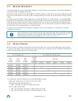
Facility Power Source: The single-phase facility power source for this product must include an overcurrent protective
device capacity as defined in the table below:
Main Inlet
Continuous Current
Rating
Mains Protection
Required
NEMA 5-15P
12 A
15 A
NEMA 5-20P
16 A
20 A
NEMA L5-20P
16 A
20 A
NEMA L6-20P
16 A
20 A
IEC C20
16 A
20 A
NEMA L5-30P
24 A
30 A
NEMA L6-30P
24 A
30 A
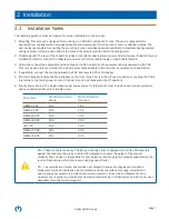
EN — These products are heavy. The flange mounting ears are designed to hold the PDU securely
against the rack mounting rails, but are NOT designed to support the weight of the product
vertically. The end user is responsible for ensuring the product’s weight is properly supported by the
rack’s infrastructure (which may require adding support rails).
FR — Ces produits sont lourds. Les oreilles de montage à bride sont conçues pour maintenir
solidement l’unité de distribution de l’alimentation contre les rails de montage, mais NE sont
pas conçues pour soutenir le poids du produit verticalement. Il incombe à l’utilisateur final de
s’assurer que le poids du produit est correctement supporté par l’infrastructure du bâti (ce qui peut
nécessiter l’ajout de rails de support).


