60
IT
EN
4.7.2.2 Montaggio
N
OTA
Le lamelle (33) e il pistone (32) determinano il freno in
estensione. Qualora fosse necessario è possibile modifi care il
comportamento della forcella in fase di estensione sostituendo
le lamelle (33) ed il pistone (32) con elementi aventi differenti
caratteristiche. Le lamelle di by-pass (30) determinano
il freno in compressione. Qualora fosse necessario è
possibile modifi care il comportamento della forcella in fase
di compressione sostituendo le lamelle (30) con altre aventi
differenti caratteristiche.
A
TTENZIONE
!
Utilizzare solamente lamelle e pistoni originali Marzocchi,
non modifi care i componenti.
Se necessario sostituire il segmento del pistone (31).
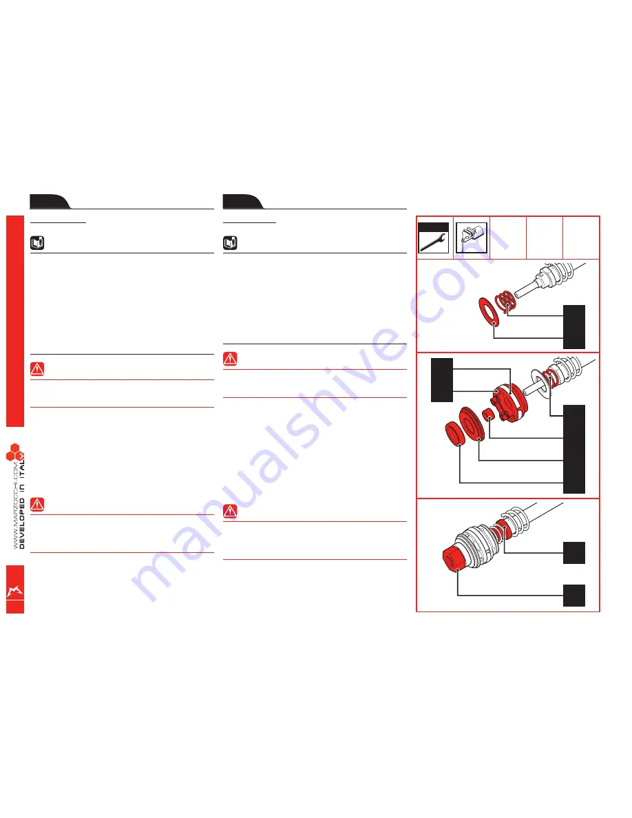
Inserire nella parte terminale dell’asta, la molla (26) e la
lamella o il pacco di lamelle di by-pass (30).
Tenendo in compressione la molla, inserire, nell’ordine,
il pistone (32) completo di segmento (31), la boccola di
centraggio lamelle (27), la lamella o il pacco di lamelle che
regolano l’estensione (33) e il distanziale calibrato (28).
A
TTENZIONE
!
Il pistone (32) deve essere orientato come indicato in
fi gura, con la parte cilindrica opposta alle lamelle che
regolano l’estensione.
Avvitare a mano il dado (34).
Servendosi di una chiave da 10 mm serrare il dado (34) alla
coppia prescritta (vedi Tabella 5 - Coppie di serraggio).
Rimuovere dalla morsa l’asta del pompante (25).
•
•
•
•
•
•
4.7.2.2 Assembly
N
OTE
Washers (33) and piston (32) are responsible for the
rebound braking. Replacing washers (33) and piston (32)
with other parts with different characteristics, lets you
change the fork behaviour during rebound if needed. The
by-pass washers (30) are responsible for rebound braking.
Whenever necessary, fork behaviour can be modifi ed during
compression by replacing the washers (30) with others
having different features.
W
ARNING
!
Use only Marzocchi original washers and pistons. Do not
modify the components.
Replace the piston segment (31) if needed.
In the end part of the rod, fi t the spring (26) and the washer
or the by-pass washer stack (30).
Compress the spring and insert the following items in
sequence: piston (32) with its segment (31), the washer
centring bushing (27), the washer or the washer stack
allowing to adjust extension (33), the calibrated spacer
(28).
W
ARNING
!
As shown in the diagram, the piston (32) must be
positioned so that the cylindrical part is opposite the
washers which regulate estension.
Tighten the nut (34) by hand.
With a 10mm spanner, tighten the nut (34) to the required
torque (see Table 5 - Tightening torques).
Remove the pumping element rod from the vice (25).
•
•
•
•
•
•
10 mm
30
26
28
33
27
26
31
32
25
34
Summary of Contents for Shiver 50
Page 1: ...SHIVER 50 MANUAL ...
Page 2: ......
Page 31: ...29 11 24 25 19 35 44 53 70 3 46 14 16 48 12 39 33 72 41 37 26 43 71 13 ...
Page 32: ...30 11 24 25 19 35 44 53 70 3 46 14 16 48 12 39 33 72 41 37 26 43 71 13 ...
Page 114: ...112 MARZOCCHI Forc SHIVER 50 AM MY2006 33 41 38 39 40 42 4 3 2 1 36 37 ...
Page 115: ......
Page 116: ...Cod 9001259 11 2006 Ed 01 ...


