20
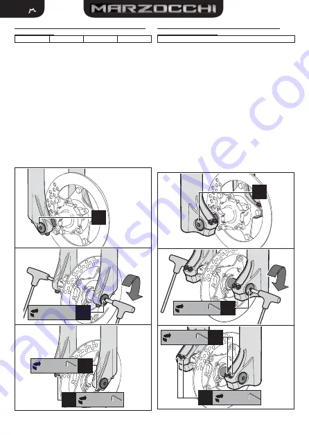
3.4.2 Wheel installation on ø32 fork with a 20 mm diameter
through-hole axle
4X
DIRT JUMPER
DJ COMP
Z1
For optimum fork performance, please follow the instructions below
when installing the wheel:
Place the wheel in between each fork.
•
Align the center of the wheel with each wheel axle clamp (see
•
3A
of
Picture 3
).
Insert the axle through the wheel axle clamp of the right fork,
•
through the wheel, and through the wheel axle clamp of the left
fork (see
3A
of
Picture 3
).
Tighten the axle to the required torque (
•
15±1 Nm
) using a 6 mm
Allen key to the axle caps (see
3B
of
Picture 3
).
Check for the proper fork-wheel alignment. To do this, begin by
•
fully compressing the fork a few times. The wheel should not
make contact with, or come close to any portion of the fork. Then
lift the front of the bicycle and spin the wheel a few times to verify
the correct alignment with the disk brake. The wheel should not
wobble from side to side or up and down. Check the owner’s
manual of the brake system for the proper speci
fi
cations.
Tighten the screw positioned on each wheel axle clamp to the required
•
torque (
6±1 Nm
) using a 4 mm Allen key (see
3C
of
Picture 3
).
3A
6 mm
15±1 Nm
3B
4 mm
6±1 Nm
3C
4 mm
6±1 Nm
3C
Picture 3 -
Wheel install on ø32 fork with a 20mm diameter through-hole axle
3.4.3 Wheel installation on ø35/ø38 forks with a 20 mm
diameter through-hole axle
888
For optimum fork performance, please follow the instructions below
when installing the wheel:
Place the wheel in between each fork.
•
Align the center of the wheel with each wheel axle clamp (see
•
4A
of
Picture 4
).
Insert the axle through the wheel axle clamp of the right fork,
•
through the wheel, and then screw it into the wheel axle clamp
of the left fork (see
4A
of
Picture 4
).
Tighten the axle to the required torque (
•
15±1 Nm
) using a 6mm
Allen key to the caps of the axle (see
4B
of
Picture 4
).
Check for the proper fork-wheel alignment. To do this, begin by
•
fully compressing the fork a few times. The wheel should not
make contact with, or come close to any portion of the fork. Then
lift the front of the bicycle and spin the wheel a few times to verify
the correct alignment with the disk brake. The wheel should not
wobble from side to side or up and down. Check the owner’s
manual of the brake system for the proper speci
fi
cations.
Tighten the screws positioned on each wheel axle clamp to the
•
required torque (
6±1 Nm
), with a “
1-2-1
” sequence, using a 4mm
Allen key (see
4C
of
Picture 4
).
4A
6 mm
15±1 Nm
4B
4 mm
6±1 Nm
4C
4 mm
6±1 Nm
4C
Picture 4 -
Wheel install on ø35/ø38 forks with a 20 mm diameter through hole axle


