background image


WIRELESS 

                                                                            FEATURES & SPECIFICATIONS 
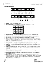
 

9. System Feature 

Ø

  Operating in UHF band frequency with synthesizer controlled. 

Ø

  The wireless microphone system with 16 selectable frequencies via Phase Locked Loop 

(PLL) circuitry makes it easy to choose non-interfered channels. 

Ø

  Diversity with two antennas to ensure the reception quality. 

Ø

  Super high sensitivity, extremely low noise transmission and reception. 

Ø

  SMT assembled PCB module ensures the quality and stability. 

10. System Specification   

Receiver 

Ø

  Carrier Frequency Range 

: UHF band 

Ø

  Frequency Stability 

±

0.005%   

Ø

  S/N ratio 

: > 94dB, at 48KHz deviation and 60dB

m

V antenna input 

Ø

  Maximum Deviation 

±

48KHz 

Ø

  Image and Spurious Rejection  : 80 dB minimum 

Ø

  Receiving Sensitivity 

: 8 dB

μ

V. 

Ø

  Selectivity 

: > 50dB 

Ø

  AF Response 

: 50Hz to 15KHz (

±

3dB) 

Ø

  T.H.D. 

: < 1% (at 1KHz) 

Ø

  Audio Output 

: Balanced and unbalanced audio outputs


Ø

  Current consumption 

: 500mA 

±

10mA 

Ø

  Power Supply 

: 12V DC 

Ø

  Dimensions 

: 420(W) x 180(D) X 45(H) mm   

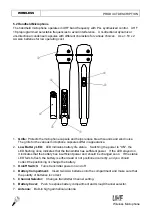
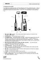
Handheld/Bodypack Transmitter 

Ø

  Carrier Frequency Range 

: UHF band 

Ø

  RF Power Output 

: 10mW (max.) 

Ø

  Oscillation Mode 

: PLL synthesized 

Ø

  Frequency Stability 

±

0.005% 

Ø

  Maximum Deviation 

±

48KHz 

Ø

  Spurious Emission 

: More than 60dB below carrier frequency 

Ø

  T.H.D. 

: Less than 1% (at 1KHz) 

Ø

  Microphone Capsule 

Handheld

: uni-directional dynamic or uni-directional electret 

condenser unit 


Lavalier

: uni-directional electret condenser unit 

Ø

  Operating voltage 

: DC1.5V x 2 AA size batteries 

Ø

  Current consumption 

: 65mA 

±

 5mA   

Ø

  Dimension (mm) 

: UF-16A: 56

j

 x263mm;UT-16A:64(W)x97(H)x24(D) 


DESIGN AND SPECIFICATIONS SUBJECT TO CHANGE WITHOUT NOTICE. 
 

10 

Wireless Microphone   

Summary of Contents for UF-16C

Page 1: ...WIRELESS MICROPHONE SYSTEM USER S MANUAL BAND...

Page 2: ...smitter 2 6 Basic Connections 7 7 Setting Up 7 1 Connecting the receiver to a mixer or an amplifier 7 2 Connecting the receiver to power 7 3 Inserting batteries into the handheld bodypack transmitter...

Page 3: ...te floor Do not place the appliance near heat sources such as radiators amplifier or etc Do not expose it to direct sunlight extremely dust excessive moisture or vibration Take out the battery from tr...

Page 4: ...SS PRODUCT DESCRIPTION 5 Product Description 5 1 Receiver The stationary receivers are used with all our 16 channel selectable transmitters The receiver operates in UHF band frequency with PLL synthes...

Page 5: ...Level Control This rotary control adjusts the receiver s output level from the microphone to line level for matching the input sensitivity of the mixer or amplifier 8 Antenna Fixed length UHF antenna...

Page 6: ...e plastics racks L2 and 2 metal connecting plates C1 Each system includes a L2 and a C1 L1 L2 C1 4 Wireless Microphone WIRELESS PRODUCT DESCRIPTION 13 Squelch Adj The squelch adjusts the output level...

Page 7: ...tes battery life status Switching the power to ON the LED flashing once indicates that the transmitter has sufficient power If the LED stayed on it indicates that the battery has insufficient power an...

Page 8: ...d soon If the status LED fails to flash the battery is either dead or not positioned correctly and you should correct the positioning or change the battery 4 Mic Line Selector optional for use with mi...

Page 9: ...SS BASIC CONNECTIONS 6 Basic Connections Connect the receiver output to the mixer or amplifier input using a standard audio cable with 3 pin XLR connectors or 6 3j phone plugs Never use the balanced a...

Page 10: ...adapter may cause irreparable damage to the unit Plug the feeder cable of the supplied AC adapter into DC IN socket on the receiver Then plug the AC adapter into a power outlet 7 3 Inserting batterie...

Page 11: ...priate position Plug the 6 3j phone plug of the optional guitar cable to the output jack on the instrument and the mini XLR 3 5j plug into audio input connector on the bodypack transmitter Switch the...

Page 12: ...high Check whether receiver is located too near metal object or there are obstructions between transmitter and receiver Sound interference Check the antenna location When using 2 or above microphone s...

Page 13: ...dB minimum Receiving Sensitivity 8 dB V Selectivity 50dB AF Response 50Hz to 15KHz 3dB T H D 1 at 1KHz Audio Output Balanced and unbalanced audio outputs Current consumption 500mA 10mA Power Supply 1...

Reviews: