RF SI
GNAL
POW ER
AF
DI
VERSI
TY
RF SI
GNAL
MI
N
VOL
UME
MAX
MI
N
VOLUME
MAX
AF
MAX
MAX
DI
VERSI
TY
VOLUME
MI
N
VOLUME
MI
N
CH
1
CH
2
CH
3
CH
4
CH
5
CH
6
CH
7
CH
8
CH
9
CH
10
CH
11
CH
12
CH
13
CH
14
CH
15
CH
16
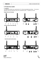
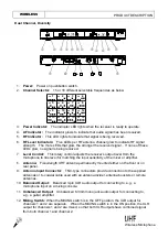
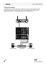
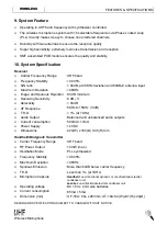
1.
Power:
Power on pushbutton switch.
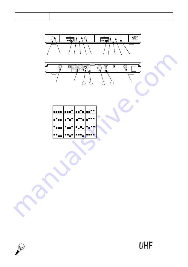
2.
Channel Selector:
15 or 16 different selectable frequencies as below.
3.
Power Indicator:
The indicator LED lights when the receiver is ready to operate.
4.
AF Indicator:
The indicator glows to indicate that audio signal has been received.
5.
RF Indicator:
This LED lights to indicate that signal is being received.
6.
RF Level Indicators:
Five LEDs per RF antenna channel glow to indicate RF signal
strength. The more LEDs that glow, the stronger the received signal. If none of these
LEDs glow, no signal is being received.
7.
Level Control:
This rotary control adjusts the receiver
’
s output level from the
microphone to line level for matching the input sensitivity of the mixer or amplifier.
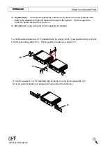
8.
Antenna:
Fixed-length UHF antenna permanently mounted either on the front or on
rear panel.
9.
Antenna Input Connector:
TNC-type connectors provide connection to the supplied
antennas or to coaxial cable used with an antenna divider, antenna boosters or remote
antennas.
10.
Balanced Output:
Balanced 3-pin XLR audio output for connecting to, e.g., a
microphone input on a mixing console.
11.
Unbalanced Output:
Unbalanced 6.3mm mono jack audio output for connecting to,
e.g., a guitar amplifier.
12.
Mixing Switch:
When the MIXING switch is in the OFF position, the XLR output for
channels 1 and 2 are separate. When the MIXING switch is in the ON position, the XLR
output for channels 1 and 2 are mixed, so that both XLR outputs have combined signal
from both channel 1 and channel 2.
3
Wireless Microphone
WIRELESS
PRODUCT DESCRIPTION
¬
-
®
¯
°
±
²
¯
°
±
²
´
µ
11
12
13
Dual Channel, Diversity
-
14
´


