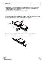
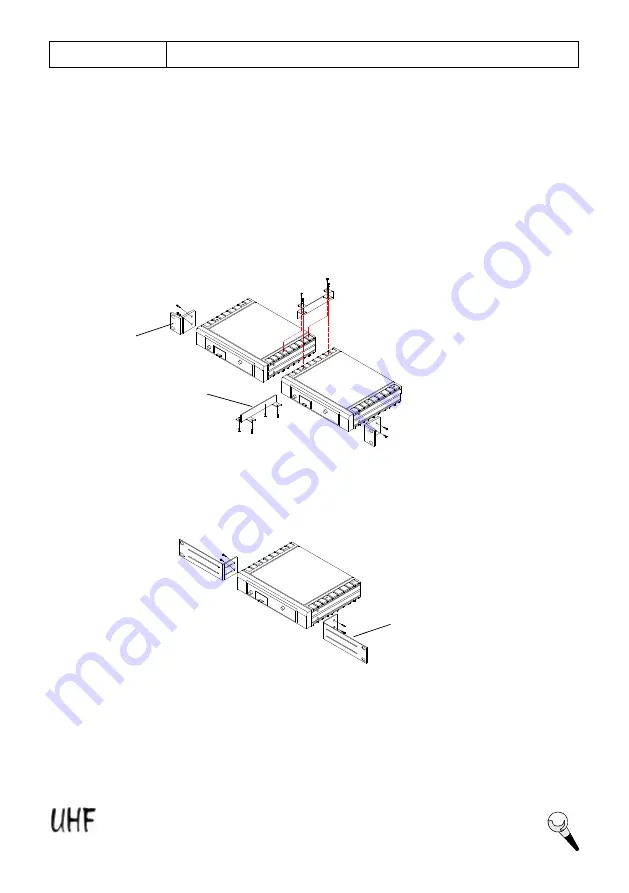
To mount a receiver in a 19
”
standard rack by using 2 L type long metal racks (L1).
(L1 is an optional product, so please purchase extra in local shops.)
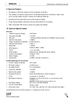
To combine two receivers in a 19
”
standard rack by using 2 short L type plastics racks (L2) and
2 metal connecting plates (C1). (Each system includes a L2 and a C1.)
L1
L2
C1
4
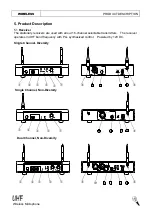
Wireless Microphone
WIRELESS
PRODUCT DESCRIPTION
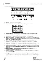
13.
Squelch Adj. :
The squelch adjusts the output level to prevent from the external noise.
Setting the squelch too high will reduce the range of the system. Set the squelch to
minimum before turning the receiver on.
14.
DC Jack:
DC input connector for the supplied AC adapter.


