background image

3

61

Instruments and controls

Dashboard  

62

Instrument panel

 68

Indicators and warning lights

 69

Instruments and gauges

 75

Controls  

81

Internal outfits 

 87

Cap3_FOTO_ing.fm  Page 61  Friday, May 30, 2008  2:17 PM

Summary of Contents for Quattroporte Automatic

Page 1: ...Owner s Manual M139_UM_ing book Page 1 Friday September 5 2008 8 19 AM ...

Page 2: ... of performance quality and safe driving In addition keep in mind that proper maintenance is an essential factor to help preserve the value of the vehicle over time and protect the environment For Scheduled Maintenance or any other operation please contact the Maserati Service Network you can trust our trained technical staff who are constantly updated and provided with the equipment required to e...

Page 3: ...3 M139_UM_ing book Page 3 Friday September 5 2008 8 19 AM ...

Page 4: ... speedway 1940 The company moves headquarters to Modena 1947 The first Granturismo is built the A6 1500 with bodywork by Pininfarina The A6GCS racing version debuts victoriously with Alberto Ascari on the Modena circuit 1954 The 250F the single seater which will allow the Maserati to win the Formula 1 World Championships makes its first appearance winning in Argentina 1957 Fangio in the 250F wins ...

Page 5: ...te Evoluzione V8 3 2 V6 2 8 3200 GT V8 1999 3200 GT V8 Automatica 2000 Alfieri Maserati Garage Customisation Programme 2001 Production begins of the Spyder with eight cylinder engine 4200 and the electro hydraulic steering wheel mounted gearbox Cambiocorsa Alfieri Maserati garages 2002 The 2 2 Coupè is presented 2003 A return to racing with the TROFEO The Quattroporte designed by Pininfarina is pr...

Page 6: ...6 Historical info Quattroporte 1963 Quattroporte 1976 Quattroporte 1965 M139_UM_ing book Page 6 Friday September 5 2008 8 19 AM ...

Page 7: ...G SYSTEM Wheel locking prevention system during braking ALC ADAPTIVE LIGHT CONTROL Automatic headlight aiming system ASR ANTI SLIP REGULATION Prevention of skidding during acceleration CAN CONTROLLER AREA NETWORK DRL DAY RUNNING LIGHTS EBD ELECTRONIC BRAKE FORCE DISTRIBUTION Electronically controlled distributor of braking force ECU ELECTRONIC CONTROL UNIT EPB ELECTRIC PARKING BRAKE ETD EMERGENCY ...

Page 8: ...tion and suggestions Automatic gearbox The vehicle is equipped with an electronically controlled automatic gearbox system which in addition to the normal automatic gearshift functions allows the user to shift gears in sequence and manually once the specific mode has been selected For correct user of the gearbox system follow the instructions given in the specific chapter of this manual Multi Media...

Page 9: ...100 km 31 mi and 62 mi After 120 km 75 mi the warning not to continue will be displayed For further information on the display please refer to chapter Tyre pressure monitoring system on page 47 WARNING Always comply with the specified wheel alignment values as this is fundamental to obtain the best performance from and the longest life of your tyres Towing the vehicle The vehicle has not been desi...

Page 10: ...ry with respect to that same symbol Danger symbols Battery Corrosive liquid Battery Explosion Fan It can start up automatically even with the engine stopped Expansion tank Do not remove the cap when the coolant is hot Coil High voltage Belts and pulleys Moving devices keep body parts and clothing away Air conditioning lines Do not open Gas under high pressure Symbols of prohibitions Battery Do not...

Page 11: ...ties and technical specifications Windscreen wipers Only use fluid of the type prescribed in the section Capacities and technical specifications Engine Use only the lubricant recommended in the section Capacities and Technical specifications Vehicle using lead free gasoline Only use lead free gasoline with an octane number R O N of no less than 95 Expansion tank Only use fluid of the type prescrib...

Page 12: ...12 Cap1_FOTO_ing fm Page 12 Friday May 30 2008 2 12 PM ...

Page 13: ...entification data Active and passive safety Instruments and controls Before you drive Using the vehicle In an emergency Capacities and technical specifications Maintenance Table of contents Cap1_FOTO_ing fm Page 13 Friday May 30 2008 2 12 PM ...

Page 14: ...1 14 Cap1_FOTO_ing fm Page 14 Friday May 30 2008 2 12 PM ...

Page 15: ...1 15 Vehicle identification data Identification plates 16 Vehicle identification plate 17 Key codes 18 Cap1_FOTO_ing fm Page 15 Friday May 30 2008 2 12 PM ...

Page 16: ...ber lift the mat and remove the guard Engine marking The engine A serial number is punched on the lower part of the crankcase in the starter motor area The engine type is indicated on the plate positioned on the front left hand door s ledge Paint identification plate The plate B is applied onto the engine compartment lid A B M139_UM_ing book Page 16 Friday September 5 2008 8 19 AM ...

Page 17: ... details A Manufacturer s name B Homologation number C Serial Number V I N D Maximum admissible weight E Maximum admissible weight on first front axle F Maximum admissible weight on second rear axle G Engine type H Vehicle version code L Assembly Number A B E F G H L C A B E F G H L C D D M139_UM_ing book Page 17 Friday September 5 2008 8 19 AM ...

Page 18: ...lace WARNING You are advised to always keep the CODE CARD number with you as this is absolutely necessary in the event of an emergency start WARNING In the event of a vehicle ownership transfer it is essential that the new owner is provided with all the keys and with the CODE CARD WARNING It is advisable to write down and keep the codes listed on the plates delivered with the keys and the remote c...

Page 19: ...1 Key codes 19 M139_UM_ing book Page 19 Friday September 5 2008 8 19 AM ...

Page 20: ...2 20 Cap2_FOTO_ing fm Page 20 Friday May 30 2008 2 14 PM ...

Page 21: ... children 27 Front and side airbags 36 MSP System 43 ASR system electronic anti skid device 44 ABS and EBD systems 45 Tyre pressure monitoring system optional 47 Parking sensors 54 Fuel cut out inertia switch 58 Cap2_FOTO_ing fm Page 21 Friday May 30 2008 2 14 PM ...

Page 22: ...at belt from the outer side of the seat and secure it by holding the fastening tang A and pulling out the belt until the tang inserts into the buckle lock B The belt is correctly engaged when the lock clicks into position To release the belts press button C The vehicle is equipped with an SBR Seat Belt Reminder system which warns the driver when the seat belt is not fastened by sounding an acousti...

Page 23: ...ways check that the cursor to which the oscillating ring is fixed is locked into one of the positions provided Therefore with the handgrip released push again downwards to allow the anchoring device to click into place in the event that it has not been released in one of the positions provided Using the rear seat belts The belts for the rear seats must be worn as shown in the figure Remember that ...

Page 24: ...oner does not require any maintenance or lubrication Tampering with the device will compromise its efficient operation If as a result of exceptional natural circumstances floods heavy seas etc the device has been in contact with water and sludge it is absolutely essential to replace it To ensure the best protection from the pretensioner secure the belt snugly across your chest and pelvis The prete...

Page 25: ...ea causing serious internal injuries Always fasten the seat belts Travelling without the seat belts fastened increases the risk of serious injury in the event of a collision even with the airbags In the event of a collision the seat belts reduce the possibility of the vehicle s occupants being thrown against the structures of the passenger compartment or out of the vehicle The airbags are designed...

Page 26: ...dren on a passenger s lap using only one seat belt for protecting both of them If the seat belt has been suffered a heavy mechanical stress for example during a collision it must be completely replaced together with its anchorages the screws fastening the said anchorages and the pretensioner In fact even if there are no visible defects the resistance level offered by the seat belt could be reduced...

Page 27: ... years of age who are less than 150 cm tall may not travel on the front seat unless using a suitable restraint system Children must always use a suitable restraint system when travelling preferably fitted on the rear seat as this is the safest position in the event of a collision When travelling with one or more child seats fitted on the rear seat of the vehicle the tables must be closed No child ...

Page 28: ... installed on the front passenger s seat this must be positioned fully back and up This is essential to help ensure maximum safety for the child All minors whose physical characteristics age height weight meet the limit values provided by the established legislation in each country must be protected by special restraint or safety systems certified child seats cradles cushions Make sure that you al...

Page 29: ...t passenger seats equipped with active passenger s airbag as this could cause serious injuries during deployment independently of the impact severity Rearward facing child seats may be used on the front passenger seat only in European vehicle models that are equipped with passenger s airbag deactivation switch In this case the driver must make sure that the airbag is deactivated by checking the re...

Page 30: ...to the instructions provided with the product Group 1 Children weighing 9 kg and more may travel in a forward facing child seat equipped with a front cushion through which the vehicle seat belt secures both the child seat and the child The figures are purely illustrative Secure the child seat according to the instructions provided with the product Certain child seats meet the requirements for grou...

Page 31: ...es to the pelvis and not to the abdominal region The figures are purely illustrative Secure the child seat according to the instructions provided with the product Group 3 Children weighing 22 kg and more only need a cushion to raise their position The depth of the child s chest is sufficient to make a distancing backrest unnecessary Children over 1 50 m in height can use seat belts like adults The...

Page 32: ...only travel if secured using suitable restraint systems We recommend that you always fit any restraint system on the rear seat as this is the safest position in the event of a collision Group Weight groups Front passenger Rear side passenger Rear central passenger Groups 0 0 up to 13 kg U U Group 1 9 18 kg U U Group 2 15 25 kg U U Group 3 22 36 kg U U If the vehicle is equipped with active passeng...

Page 33: ...ovides a special anchoring system for child seats which uses two metal brackets B positioned between the seat cushion and backrest These metal brackets are easily identifiable through the label bearing the logo shown below The seats designed for Isofix child seats installation can always be fitted with standard child seats you can actually install a standard and an Isofix child seat at the same ti...

Page 34: ...D ISO R2 IUF IUF C ISO R3 IUF IUF 1 Group I from 9 to 18 kg D ISO R2 IUF IUF C ISO R3 IUF IUF B ISO F2 IUF IUF B1 ISO F2X IUF IUF A ISO F3 IUF IUF 1 IUF Isofix position suitable for forward facing Isofix type child restraint systems of the universal class approved for use in the relative weight group X Isofix position not suitable for Isofix child restraint systems in this weight group and or in t...

Page 35: ...with the brackets C then push the seat until you hear it click in place which indicates it is properly secured check that the child seat is correctly locked by trying to move it with strength the incorporated safety mechanisms prevent the child seat from being improperly fitted if only one of the attachment fittings is locked pass the strap G underneath the rear headrest and anchor it onto the chi...

Page 36: ...2 36 Front and side airbags Front and side airbags 3 2 6 4 8 9 1 16 15 14 10 12 13 11 17 5 7 18 M139_UM_ing book Page 36 Friday September 5 2008 8 19 AM ...

Page 37: ...and with a larger size bag full size airbag on the passenger side The front airbags driver s and passenger s are safety devices designed to protect the occupants in the event of head on collisions of medium high severity They act by placing a cushion airbag between the occupant and the steering wheel or the dashboard In the event of a collision an ECU processes the deceleration signals detected by...

Page 38: ...n Passenger s airbag full size airbag The passenger s airbag has been designed and calibrated to enhance the protection level provided to a person wearing the seat belt Therefore when fully deployed it fills the largest part of the space between the passenger and the dashboard SERIOUS DANGER the vehicle is fitted with a passenger side airbag Before fitting any rearward facing child seat on the fro...

Page 39: ...rearward facing restraint systems The warning light on the instrument panel and the LED on the roof panel remain permanently illuminated until the passenger airbag is reactivated WARNING should the warning light passenger s airbag off malfunction its failure will be shown on the display WARNING The deactivation of the front passenger s airbag does not affect the operation of the side airbag When t...

Page 40: ...gs front and rear based on different criteria according to the type of impact Failure of one or more systems to activate is not indicative of a system malfunction In the case of low impact lateral collisions for which the retaining action of the seat belts affords adequate protection the airbags do not inflate It follows that the front airbags on driver and passenger side do not replace or substit...

Page 41: ... Service Network to have the system deactivated WARNING If the vehicle is sold the new owner must be informed of the aforesaid instructions for use warnings and he she must also be provided with the Owner s Manual General warnings When the ignition key is turned to the MAR position the warning light comes on but it must switch off after approx 5 seconds If the warning light fails to come on at thi...

Page 42: ...is run into by another vehicle Therefore even with the vehicle stationary children must be secured by the specific child restraint systems installed on the passenger seat and the passenger airbag must be deactivated On the other hand the airbags will not inflate in case of collision with the vehicle stationary and the key removed from the ignition block failure of the airbags to inflate in these c...

Page 43: ...riving this condition is signalled by the amber warning light that illuminates both on the instrument panel and on the multi function display accompanied in the latter case by the message MSP unavailable go to dealer When the engine is started the system malfunction is indicated by the warning light switching on WARNING In the event of a fault with the MSP disabled the vehicle will react as if it ...

Page 44: ...ed and can be cut out by pressing button A for about 2 seconds Press button A again to reactivate the system The dark yellow warning light on the instrument panel flashes during all the activation phases Fault indicators In the event of a fault the system is automatically disabled and cannot be reactivated While driving this condition is signalled by the amber warning light on the instrument panel...

Page 45: ...the efficiency of the standard braking system The failure will be indicated through the lighting up of the red warning light with the letters ABS on the instrument panel In this case we recommend you contact the nearest Maserati Service Network centre which thanks to the self diagnostics system the vehicle is equipped with will be able to identify the problem immediately The vehicles must be equip...

Page 46: ...e fluid level is below the minimum notch top up with the recommended fluid and contact the Maserati Service Network immediately to have the system checked Brake fluid leaks impair the operation of whatever braking system both the standard types and those fitted with anti lock system System performance in terms of active safety is not a reason for the driver to run unnecessary risks The driving sty...

Page 47: ...alibration button to the vehicle s electrical system The system warns the driver that there is a drop in tyre pressure This warning does not exempt the driver from periodically checking the tyres and from complying with the prescribed tyre pressure levels WARNING The system stores the tyre pressures as a reference rate therefore tyres must be inflated to the prescribed pressure System calibration ...

Page 48: ...vent occurs the malfunction is viewed in the place of the information on tyre pressure levels The malfunction is displayed for a time equal to its entire display cycle When the display cycle ends the tyre pressure screen page becomes available again and the multi function symbol indicating the malfunction is displayed in the specific area until the malfunction is rectified B M139_UM_ing book Page ...

Page 49: ...shold screen page 2 is displayed for 10 seconds after which the system will display the screen page previously active When the key is subsequently turned back to ON or when the MODE button is pressed if the malfunction persists the display will show screen page 2 once again The system may not know what wheel is originating the malfunction indication and therefore is not capable of indicating the w...

Page 50: ... and therefore is not capable of indicating the wheel involved As a consequence in addition to the warning light permanently illuminated on the instrument panel the display will show screen page 5 The display strategy of this screen page follows the same logic applied for screen page 4 previously described Run Flat tyre puncture If the vehicle is equipped with Run Flat tyres in the event of a tyre...

Page 51: ...ed value of the km that can still be driven depending on the distance covered from the previous puncture and displays the pages 9 alternately If the driver presses the MODE button with the Escape function during the tyre punctured condition but not in maximum speed conditions and with the tyres still in a condition to continue driving the summary symbol will be displayed in the dedicated warning l...

Page 52: ... show screen page 11 Subsequently the screen page previously active is displayed once again and the warning light on the instrument panel illuminates permanently The system can be calibrated by means of the specific button see page 47 The information page that shows the pressure value for each tyre cannot be recalled Tyre pressure monitoring system failure Tyre pressure monitoring system failure S...

Page 53: ...n the warning light which is permanently illuminated on the instrument panel will flash for 90 seconds after which it will remain permanently on until the situation is corrected The information page that shows the pressure value for each tyre cannot be recalled System not active After the key is turned on in the case that the system has been deactivated by means of the diagnostic tester screen pag...

Page 54: ...button illuminates with an amber colour To deactivate the front sensors press button A once again When reverse gear is disengaged all the sensors remain active The rear sensors remain active for about 10 seconds or until a speed of approx 10 Km h 6 mph is exceeded The front sensors remain active until a speed of about 10 Km h 6 mph is exceeded When the rear or front sensors are activated an acoust...

Page 55: ...the Configuration menu selecting the Define vehicle parameters option then the Stop Go parking option and setting it to Activation With the Stop Go function active the front sensors will automatically be activated in all conditions where the vehicle speed goes below 8 Km h 5 mph WARNING The Stop Go function is only available if the vehicle is equipped with front parking sensors For the system to o...

Page 56: ...nd at the rear of the vehicle In the event of an obstacle located in a central area this will be detected at distances of less than 0 9 m at the front and 1 50 m at the rear depending on the type of obstacle and its dimensions If the obstacle is located in a lateral position it will be detected at distances of less than 0 6 m 2 feet M139_UM_ing book Page 56 Friday September 5 2008 8 19 AM ...

Page 57: ...work to have the system checked During parking manoeuvres always be extremely careful with obstacles that might be located above or below the sensors In fact in certain circumstances objects located near the rear of the vehicle are not detected by the system and therefore could damage the vehicle or be damaged themselves The signals transmitted by the sensors can also be altered by damage to the s...

Page 58: ...ply system do not reactivate the switch in order to avoid fire risks The activation of the inertia switch results in all the doors and the luggage compartment unlocking and in the internal dome lamp and the four direction indicators switching on Resetting the switch Turn the ignition key to the STOP position Check that there is no leakage from the fuel system If no leaks are found reset the inerti...

Page 59: ...2 Fuel cut out inertia switch 59 M139_UM_ing book Page 59 Friday September 5 2008 8 19 AM ...

Page 60: ...3 60 Cap3_FOTO_ing fm Page 60 Friday May 30 2008 2 17 PM ...

Page 61: ...61 Instruments and controls Dashboard 62 Instrument panel 68 Indicators and warning lights 69 Instruments and gauges 75 Controls 81 Internal outfits 87 Cap3_FOTO_ing fm Page 61 Friday May 30 2008 2 17 PM ...

Page 62: ...3 62 Dashboard Dashboard 1 2 35 34 3 4 5 7 6 8 9 10 11 12 13 10 37 36 14 15 16 17 33 32 31 30 28 29 27 27 26 21 24 25 23 22 20 18 19 3 2 1 M139_UM_ing book Page 62 Friday September 5 2008 8 19 AM ...

Page 63: ...ton 16 Glove compartment 17 Passenger s airbag 18 Multi Media System Display 19 Multi Media System Controls 20 Air conditioning and heating system controls 21 Hazard button 22 Automatic gearshift lever 23 Ashtray with cigarette lighter 24 Electric handbrake engagement disengagement lever 25 Gear display 26 Ignition steering lock switch 27 Multi Media System Controls repeated on the steering wheel ...

Page 64: ...on F Sunshade raising lowering button Ref 27 Multi Media System Controls repeated on the steering wheel A Increases the sound system volume B Decreases the sound system volume C Voice control function activation deactivation Navigator Mode Enables the guiding voice during the trip guidance and also displays information pertaining to the guidance session D Button pressed briefly Telephone mode acti...

Page 65: ...essed at length CD audio mode track fast rewind G Mode selection radio CD or Jukebox H Mute function on off I Radio mode radio frequency shift to the next station in preset steps starting from the station currently tuned CD MP3 Jukebox and USB mode selects next folder Menu scrolls through the menus J Radio mode radio frequency shift to the previous station in fixed steps starting from the station ...

Page 66: ... s door A Rear power window lock unlock control B Easy entry exit system deactivation device C Rear left hand power window control D Rear right hand power window control E Front left hand power window control F Front right hand power window control G External rear view mirror control Rear tunnel controls A Door lock unlock buttons B Sunshade raising lowering buttons A B C D E E G C F D B A A B M13...

Page 67: ...Alarm system motion sensors cut out C Telephone handsfree microphone D Tyre pressure calibration control E Passenger s airbag deactivation warning light Ref 37 Controls on front dome lamp fixture F LH side light switch G Central light switch H RH side light switch A B A B C D E H F G M139_UM_ing book Page 67 Friday September 5 2008 8 19 AM ...

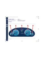
Page 68: ...trument panel 1 Fuel level gauge and low fuel warning light 2 Tachometer 3 Display 4 Rev Counter 5 Coolant temperature gauge and high temperature warning light 1 2 3 4 5 M139_UM_ing book Page 68 Friday September 5 2008 8 19 AM ...

Page 69: ...n the fuel supply ignition and emission control systems The failure could cause high exhaust emissions loss of performance poor vehicle handling and high consumption levels In these conditions you can proceed slowly without demanding engine performance or high speeds Prolonged use of the vehicle when the warning light is on can cause damages For this reason you should contact the Maserati Service ...

Page 70: ...indicates an EBD system failure In this case do not apply the brakes suddenly since this may cause an early locking of the rear wheels Drive with the greatest care and have the system immediately checked by the nearest Centre of the Maserati Service Network If the warning light comes on while driving check the brake fluid level immediately If the fluid level is below the minimum level there could ...

Page 71: ...anual emergency deactivation procedure must be performed to release the parking brake see page 181 Excessive temperature If the vehicle has been stationary key to STOP for about 15 minutes without using the parking brake and the warning light illuminates again after restarting the engine slowly drive to the nearest Centre of the Maserati Service Network Parking brake system overhaul The EPB system...

Page 72: ...larly with consequent high temperature in the exhaust system IF THE WARNING LIGHT IS ACCOMPANIED BY THE MESSAGE HIGH CATALYSTS TEMPERATURE SLOW DOWN the temperature of the catalytic converters is too high The driver must slow down immediately until the warning light turns off IF THE MESSAGE EXCESSIVE CATALYSTS TEMPERATURE DO NOT DRIVE ON APPEARS AFTER DECELERATING the temperature in the catalytic ...

Page 73: ...ailure When driving it indicates a malfunction in the suspension system Finger trap prevention system failure This indicates a failure in the windows finger trap prevention system Before and during activation of the power window always check that the passengers are not exposed to the risk of injury both by the moving window and by personal objects that could be dragged or hit by it Vehicle protect...

Page 74: ...ce Network Automatic gearbox setting This indicates that the automatic gearbox feature is active Vehicle SPORT setting When the button that sets the vehicle to the SPORT mode is pressed WARNING The SPORT mode changes the vehicle driving features WARNING SPORT mode should not be activated if the road surface is in rough or slippery WARNING In low and medium grip conditions e g rain snow ice sand et...

Page 75: ...18 litres 4 UK gal of fuel in the tank Tachometer 2 It indicates the vehicle speed The gauge starts providing data when 4 Km h 2 5 mph are exceeded Rev Counter 4 It indicates the engine s r p m Correct driving allows the driver to exploit the engine performance fully without the need of over revving M139_UM_ing book Page 75 Friday September 5 2008 8 19 AM ...

Page 76: ...setting the parameters for the information that can be recalled The screen page displayed following the initial check cycle in normal working conditions standard screen page contains the following information A Date B Time C Gear engaged D Driving mode E Total odometer F Trip odometer A B or vehicle speed repetition G Other symbols that may be displayed in icon form H Outside temperature From the ...

Page 77: ...l flash for 10 seconds after which the non flashing information previously viewed is restored and By means of the K and L buttons the user can adjust the instrument panel brightness When the Option Selection screen page is viewed these buttons can be used to select choosing between Trip Odometer A and Trip Odometer B the information to be repeated on the display In fact by selecting Odo A or Odo B...

Page 78: ... MODE J button the user will display information about the Tyre Pressure This screen page is displayed for 10 seconds and in normal conditions it will appear as shown in figure 1 furthermore the system acknowledges the following conditions system temporarily not active es external radio interference system not calibrated e g tyre replaced system failure system not active if it is disabled by the d...

Page 79: ...ve system activation deactivation In both cases the screen pages are displayed for 10 seconds and appear as shown in Figures 2 and 3 Option Selection Screen Page Briefly press the MODE button to display the screen page and select the desired value among the following ones TRIP A distance TRIP B distance Current speed repetition Passenger compartment temperature on the driver s side which will be d...

Page 80: ...PM indicator this setting shall be ignored until the repetition function is disabled see page 84 of the Multi Media System manual Multi Media System configuration menu By accessing the Configuration mode the user can set up the vehicle features The parameters that can be set are the following Display configuration select the colour choosing between day night mode or automatic setting adjust the br...

Page 81: ...e activated the direction indicators control is disabled Controls to the left of the steering wheel Front fog lights Press button C to switch on the front fog lights They only work with the position lights or low beams on The LED on the button switches on when the lights are on Rear fog lights Press button D to switch on the rear fog lights They only work with the front fog lights or low beams on ...

Page 82: ... hand side of the vehicle This button can be operated only when the ignition key is removed or in the STOP position Rear central headrest tilting Press button G to tilt the rear central headrest The headrest can be then repositioned manually Before doing so always check that the passengers are not exposed to the risk of injury both by the moving headrest and by personal objects that could be hit b...

Page 83: ...el display controls see page 77 Setting the instruments and gauges brightness With the external lights turned on press button J or K to increase or decrease the brightness for the instruments and gauges Mode Pressing button L will select the screen pages to be viewed on the instrument panel display AudioPilot Sensor The sensor M detects the surrounding noise and consequently adjusts the stereo equ...

Page 84: ...d grease WARNING If within a time period of 25 seconds the sunshades are raised and lowered at least 4 times the relative control will disable them for 30 seconds Before disabling the sunshade the system will complete the movement in progress The last movement accepted will be opposite to the starting movement SPORT mode Press button R to select SPORT mode which activates Automatic Gearbox and set...

Page 85: ...e EPB see page 181 Press the button T to deactivate reactivate the function MSP System The MSP system activates automatically every time the engine is started It is possible to disconnect or reconnect the system while driving by pressing button U To avoid deactivating the system inadvertently the button must be pressed for about 2 seconds to turn the MSP system off When the system is deactivated t...

Page 86: ... When this function is deactivated the led on the button will flash for 3 seconds and then turn off Tyre calibration button To calibrate the system with the ignition key in position MAR press button X for a time ranging from 4 to 10 seconds The system will take a maximum of 20 minutes to complete the calibration procedure with the vehicle in motion The detected situation will then be shown on the ...

Page 87: ...hat passengers are not exposed to the risk of injuries caused both by the moving roof and by personal objects dragged or hit by the sunroof itself When you exit the vehicle always remove the ignition key to avoid that the sunroof if operated inadvertently becomes a danger for passengers remaining onboard WARNING Do not open the sunroof if there is ice on it risk of damage Opening and closing The s...

Page 88: ...hts will switch off after about 10 seconds Upon removing the key from the switch and activating the centralised door lock with the remote control the dome lamps turn on for about 10 seconds In the event of a collision causing the inertia switch to turn on the dome lights switch on automatically for approx 15 minutes Rear dome light The dome light includes a central light and two reading lights The...

Page 89: ...e mirror protective cover Before raising the visor close the mirror cover Clock The clock is adjusted automatically by setting the time with the Multi Media System The clock lights up when the external lights are turned on Rear window sunshade The electrical sun shade works with the ignition key in the MAR position The switch buttons are located both on the front and on the rear dashboard WARNING ...

Page 90: ...Housed on the rear doors they roll up automatically To pull out the sunshade pull on the grip K and latch it into the catches L located on the top edge of the door Front ashtray and cigarette lighter They are found on the central console hidden by a cover To open the cover slide it forward Pressing button M operates the cigarette lighter After about 20 seconds this returns automatically to the ini...

Page 91: ...ned in the lower part of the dashboard on the passenger side it can be opened pressing button O The latter only works with the ignition key turned to MAR and for about 10 minutes after having extracted the key or rotated it to the STOP position The compartment is lit by a courtesy light when it is open To ensure passenger safety the compartment must always remain closed while driving If the button...

Page 92: ...artment pull the armrest holding it from the handgrip To activate the air conditioning ventilation inside the compartment move control Q upwards To stop it lower back the control WARNING The temperature of the air inside the beverage cooler is the same that as that coming out from the air conditioning heating vents it therefore depends on the temperature set via the relative control panel Map pock...

Page 93: ...ndicated on the table When travelling with one or more child seats fitted on the rear seat of the vehicle the tables must be in the closed position When closing the table always guide it down risk of crushing WARNING As the table is not equipped with holding devices do not place open drinks containers on the tables during the journey as the surrounding upholstery could be stained or damaged if the...

Page 94: ...manufacturer must provide together with the device to be controlled If you do not have this manual request it from the supplier Before opening or closing a gate or door make sure that the procedure can be performed in thorough safety i e make sure that you can see the whole range of action of the gate or door and also check that there are no persons animals or other objects within this range Gener...

Page 95: ...mming press and hold buttons M and O after about 20 seconds the LED P starts flashing release the buttons hold the remote control for the device to be controlled close to the HomeLink control panel 0 30 cm simultaneously press and hold the button on the hand held remote control and one of the three HomeLink buttons M N or O if the programming procedure has been successfully completed the LED P wil...

Page 96: ...ditions a LED will illuminate WARNING Normally after this operation you have 30 seconds to start the next one Briefly press the HomeLink button you have chosen to control the device press it a second time when it is released the operation should be completed For some types of motors the button might have to be pressed a third time Reprogramming an individual button If you wish to program activatio...

Page 97: ...l three buttons are deleted simultaneously To delete proceed as follows press and hold buttons M and O after about 20 seconds the LED P starts flashing release the buttons WARNING It is advisable to carry out the Home Link deletion procedure when selling the vehicle M139_UM_ing book Page 97 Friday September 5 2008 8 19 AM ...

Page 98: ...4 98 Cap4_FOTO_ing fm Page 98 Friday May 30 2008 2 44 PM ...

Page 99: ...112 Electronic alarm system 113 Front seats 117 Rear seats 121 Rear view mirrors 124 Steering wheel 126 External lights and direction indicators 127 Windscreen wiper washer and headlight washers 131 Maserati Multi Media System 133 Air conditioning and heating system 141 Bose Surround Sound 148 Cap4_FOTO_ing fm Page 99 Friday May 30 2008 2 44 PM ...

Page 100: ...lour green red LED E which indicates the locks status locked unlocked The red LED lights up for 3 seconds after the locks are engaged and the green LED for the same amount of time when they are released WARNING The door LEDs remain lit for approximately 3 seconds and therefore in normal conditions the LEDs are switched off When the alarm system is switched on and the doors are locked the LEDs on t...

Page 101: ...osed properly this is signalled by the relative warning lights on the instrument panel display switching on accompanied by the messages Door open or Doors open Rear door internal locking device child safety device This device is used to prevent the rear doors from being opened from the inside It is activated deactivated by turning using the tip of the ignition key the device J to position 1 device...

Page 102: ...eed to have the vehicle tested on a roller bench with nobody onboard you must verify through the vehicle set up menu that the automatic door locking feature that is activated upon exceeding 20 Km h is disabled or that a window is open or that you have ad additional key left out of the vehicle Door release in the event of an accident In the event of a collision with activation of the inertia switch...

Page 103: ... fitted on the lower side of the door panel Underdoor courtesy light Each door panel is fitted on the lower side with a courtesy light L to illuminate the area where passengers enter exit the vehicle Gearshifting is always active and may be performed even when one or more doors the engine compartment lid or the luggage compartment lid are open Therefore in these conditions take great care to avoid...

Page 104: ...ey in the MAR position Improper use of the sunroof can however be dangerous even if the vehicle is equipped with the finger trap prevention system Before and during activation of the power window always check that the passengers are not exposed to the risk of injury both by the moving window and by personal objects that could be dragged or hit by it When getting out the vehicle always remove the i...

Page 105: ...ly closed or until the button is released WARNING Before leaving the vehicle it is advisable to check the windows are completely closed To activate the centralised windows and sunroof opening keep button F on the remote control pressed down for over 2 seconds after the doors have been opened the power windows and sunroof move automatically until fully open or until the button is released WARNING B...

Page 106: ...upport stays To close the lid lower it to about 20 cm 8 in from the engine compartment and let it drop it will close automatically Always check that the engine compartment lid is properly closed to prevent it from opening while travelling Gearshifting is always active and may be performed even when one or more doors the engine compartment lid or the luggage compartment lid are open Therefore in th...

Page 107: ...e vehicle is travelling the luggage compartment can only be opened when the ignition key is removed on or in the STOP and ACC position Raising the lid is facilitated by the action of the gas struts The struts are calibrated to guarantee proper operation with the weights specified by the manufacturer Arbitrary additions of objects spoilers parcel racks etc can jeopardise proper operation and safety...

Page 108: ...n attached to the flap by means of the respective hook B The cap is linked to the filler neck with a strap so that it cannot be misplaced while refuelling The flap must be re closed manually Before closing the flap check that the fuel filler cap is fully tightened Do not bring naked flames or lit cigarettes close to the filler risk of fire Also avoid putting your face close to the filler neck so a...

Page 109: ...is removed the from the STOP position the protection system will activate the engine immobilizer When the key is turned to MAR upon engine start up 1 If the code is acknowledged the warning light CODE on the instrument panel will off within a second while the EOBD warning light once the ECU diagnosis cycle has been completed will switch off after about four seconds Under these conditions the prote...

Page 110: ...rdering additional keys remember that memorising up to maximum of 7 keys must be carried out on all the keys including those already in your possession Contact the Maserati Service Network directly bringing with you all the keys in your possession the Maserati CODE system CODE CARD the electronic alarm system CODE CARD a personal ID and the identification and registration documents proving ownersh...

Page 111: ... equal to the second digit of your CODE CARD press down the accelerator pedal and keep it pressed 6 Proceed in the same manner for the remaining digits in the code on the CODE CARD 7 When the last digit has been entered keep the accelerator pedal pressed down The EOBD warning light comes on for 4 seconds and then goes off you can now release the accelerator pedal 8 A quick flashing of the EOBD LED...

Page 112: ...within 30 seconds you will need to turn it back to MAR and then to STOP to obtain a further 30 seconds within which to remove the key In the event that the key unlocking system fails or if it is not possible to shift the gearshift lever to P to remove the key you must turn it to STOP then remove the cap A using a pen or sufficiently pointed tool then press the button just uncovered and at the same...

Page 113: ...e direction indicators will flash once the system beeps the red LEDs on the front door panels flash the vehicle s centralized door locking system is activated and locks the doors The alarm system becomes operative after approximately 25 seconds and the alarm is activated if a door is opened the luggage compartment lid is opened the engine compartment lid is opened someone attempts to enter the veh...

Page 114: ...work to have the system checked Deactivation To switch the electronic car alarm off press button B on the key the direction indicators flash twice the system gives a double beep the red LEDs on the front door panels switch off the centralized door lock system is activated and the doors are unlocked The alarm system is off and it is therefore possible to get into the vehicle and to start the engine...

Page 115: ... you turn the ignition key Ministerial homologation The electronic alarm system is compliant with the current legislation covering radio frequencies in each Country The homologation number can be found at the end of this manual before the table of contents For those markets that require the transmitter and or receiver marking the approval number is found on the component Ordering extra radio opera...

Page 116: ...e corresponding function does not activate replace the remote control battery after checking the operation of the alarm system functions with the other remote control To replace the remote control battery extract the key fitting by pressing button E undo the screw F remove the battery support G extract the battery H from its retaining ring fit a new battery of the same type observing the indicated...

Page 117: ...ment Push lever A on the outer side of the seat forward or back Height adjustment Grip lever A at the centre and push it down or up Seat inclination adjustment tilting Front part of seat push the front end of lever A up or down Rear part of seat push the rear end of lever A up or down Seatback rake adjustment Push lever B forwards or backwards to raise or lower the backrest Adjusting the headrest ...

Page 118: ...a massage function in the thigh and lumbar region areas The function can be switched off by pressing button K again The massage cycle lasts 5 minutes in total after which the function cuts out and the previous settings are restored Self adaptive system The system is activated by pressing button L and it enables the seats to adapt themselves to the occupant s body thanks to the inflatable bags If t...

Page 119: ...y memorised with that particular button To recall one of the stored positions with the door open press the relative button 1 2 or 3 briefly To recall the a stored position with the door closed press the corresponding button until hearing a tone that confirms the seat has stopped WARNING To stop the seat press one of the buttons 1 2 or 3 or one of the adjustment controls WARNING Malfunctioning of t...

Page 120: ...on is activated when the door is opened only if the ignition key has been extracted or is in position STOP On re entry the driver finds the seat and steering wheel still in these positions After sitting down and closing the door upon turning the key to position MAR both the seat and the steering wheel return to their normal driving positions The function can be deactivated by pressing button Q Dea...

Page 121: ...cated on the door panel next to the seat you wish to adjust either upwards or downwards Armrest The rear armrest is mobile and can be folded up into the seatback To lower it pull the handle B To close it pull it upwards then push it back into its seating Inside the armrest there is a pocket change compartment containing a 12 volt power socket To access the compartment lift the armrest cover using ...

Page 122: ... the previous settings are restored To activate the massage feature press button 1 left hand seat or 7 right hand seat If the button is pressed again the function is switched off Ventilation system By means of two fans one in the cushion and one in the seatback this system provides ventilation for the thigh and back areas The relative wheel button can also be used to adjust the intensity of the ve...

Page 123: ...ht hand controls are used to adjust the right hand seat while the right hand controls adjust the left hand seat 1 7 Massage activation deactivation 2 8 Lumbar support increase decrease 3 6 Ventilation activation and adjustment 4 5 Heating activation and adjustment 9 Front passenger seat backward forward movement Winter Pack optional With this type of equipment the heating system is installed in th...

Page 124: ...allows each mirror to be adjusted with four movements up down right left Bring the selector back to the centre to prevent mirror position being changed involuntarily Mirror retraction By turning the selector switch A to the lower central position both the mirrors fold inwards to facilitate parking in narrow spaces If the selector switch is set back in the upper central position the mirrors return ...

Page 125: ...at is more the mirror positions can be adjusted for both the normal travelling direction and for reverse manoeuvring WARNING Never retract or open the mirrors by hand to avoid damaging the powering mechanism The mirrors must always be in the open position when the vehicle is moving Electrochromic external rear view mirrors optional The particular feature of these mirrors is that they gradually dar...

Page 126: ... exit system The easy entry exit system makes it easier for the driver to get in and out the vehicle In fact before the driver gets out the seat moves back and the steering wheel rises The function is activated when the door is opened only if the key has been extracted or is in position STOP On re entry the driver finds the seat and steering wheel still in these positions After sitting down and cl...

Page 127: ...panese market these lights are not functioning for all the other markets where by law they may not be turned on they can be deactivated through the Multi Media System Parking lights The parking lights work only with the ignition key in the STOP or ACC positions or with the key removed They are activated by turning the light switch to position It is harder to turn the switch to position than to the...

Page 128: ...tched on automatically only the front fog lights will come on Therefore the user will have to switch the rear fog lights on manually if these are required The responsibility for switching on the lights depending on the daylight and the regulations in force in the country of use always lies with the driver The automatic system for switching on and off the external lights is to be considered as an a...

Page 129: ...ators if you move it down you activate the left hand direction indicators This function is useful when overtaking or changing lanes High beams To switch on the high beams with the light switch in position 2 push the left hand lever towards the dashboard Pull the lever towards the steering wheel again to switch off the high beams and switch on the low beams WARNING For the use of the high beams fol...

Page 130: ...me appears on the instrument panel display for 20 seconds and the lights activation time is displayed When the function is active every time the flash control is operated the time the lights remain on is increased by 30 seconds with a maximum total time of 210 seconds The display will show the value of the time set If the flash control is operated for over 2 seconds the function is deactivated and...

Page 131: ...ctivated the windscreen wiper starts automatically Releasing the lever cuts off the jet of fluid whilst the blades continue to wipe for a little while WARNING Do not start the windscreen washer during the cold months until the windscreen has warmed up If it has not warmed up the liquid could freeze on the glass and block the view WARNING If there is ice or snow on the windscreen do not activate th...

Page 132: ...tent wipe to a minimum slow intermittent wipe If the engine is turned off during automatic windscreen wiper operation with the lever in position B to reactivate the function the next time the engine is started the lever must be moved to A stop position then returned to position B Before cleaning the front windscreen for example in service stations make sure the rain sensor is deactivated or that t...

Page 133: ...e for reaching the set destination The suggestions provided by the navigation system do not relieve the driver from full responsibility for the manoeuvres made through traffic while driving or from compliance with road regulations and other provisions regarding road traffic The person driving the vehicle is always and in any case responsible for safe driving on the road The system controls and mai...

Page 134: ...stem Controls A Display B Multi Media System Controls C Front automatic heating air conditioning controls D Rear automatic heating air conditioning controls optional C A B D M139_UM_ing book Page 134 Friday September 5 2008 8 19 AM ...

Page 135: ...io CD Jukebox and USB mode audio adjustment music ambience bass treble Fr Rr balance L R Balance loudness automatic volume adjustment With Bose Hi Fi system optional Radio CD Jukebox and USB mode audio adjustment bass treble front rear equalizer LH RH equalizer Center Point 10 Button pressed briefly Radio mode Automatic search for the next radio station CD Jukebox and USB mode go to next track Men...

Page 136: ...riefly Radio mode Automatic search for the previous radio station CD Jukebox and USB mode goes to previous track if selected within the first 3 seconds of track playing otherwise the track is played again from the beginning Menu scrolls through the menus Button pressed at length CD audio mode track fast rewind 16 Button pressed briefly Radio mode recalls the stations stored 1 6 Telephone mode dial...

Page 137: ...ht hand side of the screen radio map onboard computer TRIP telephone 22 Increases the audio volume 23 Decreases the audio volume 24 Button pressed briefly Radio mode searches for the first tunable station with a higher frequency CD Jukebox and USB mode next track selection Button pressed at length CD audio mode track fast forward 25 Button pressed briefly Radio mode searches for the first tunable ...

Page 138: ...g the MODE button If in Configuration mode the Radio option under Info repetition on instrument panel is activated the radio station selected or SEARCH is displayed on the instrument panel depending on the operation in progress Press the button 30 or the knob 12 to access the main functions enter frequency disable RDS frequency search deactivate Radio Text CD MP3 and Jukebox The CD MP3 and Jukebox...

Page 139: ...is socket cannot be used for data exchange USB Full Socket This socket allows you to exchange data and power the connected source If there are MP3 files on the USB key they will automatically start playing This will not occur if you are already listening to a music source in this case you need to select the USB function by repeatedly pressing the SRC 2 or 26 button On board TRIP computer The On Bo...

Page 140: ...riving deviate route route options consult traffic info move map Bose Infotainment optional The vehicle may come equipped with Bose Infotainment an advanced user interface which combines innovative and exclusive technical features to provide entertainment navigation communication and information functions within a single system In addition this vehicle is equipped with Bose Surround Sound System a...

Page 141: ...4 Air conditioning and heating system 141 Air conditioning and heating system A A B E F H H G C D D A M139_UM_ing book Page 141 Friday September 5 2008 8 19 AM ...

Page 142: ...s with direction option These can be positioned vertically and longitudinally by means of control I Using control J the air flow distribution can be adjusted Vents A F and G have the following said features Fixed air distribution vent These cannot be adjusted in any way and are designed specifically for demisting defrosting or cooling certain areas Vents B C D E and H have the said features I J M1...

Page 143: ... the right hand side 6 air conditioner system s compressor activation deactivation button 7 single dual zone selection button 8 defrosting demisting activation deactivation button 9 for air recirculation activation deactivation button 10 automatic manual system control button 11 heated rear window activation deactivation button 12 rear instrument panel activation deactivation button 10 9 1 11 7 3 ...

Page 144: ...stem control button 16 right hand temperature setting 17 single dual zone selection button 18 fan speed adjustment control 19 air conditioner system compressor activation deactivation button 20 3 position air distribution setting on the left hand side 21 3 position air distribution setting on the right hand side 14 17 18 19 16 13 15 20 21 B M139_UM_ing book Page 144 Friday September 5 2008 8 19 AM...

Page 145: ...lly the other automatic functions will not be affected The following parameters functions can be set modified manually left hand right hand side air temperature fan speed air distribution setting on 7 positions left right compressor activation single dual zone distribution priority defrosting demisting function MAX DEF air recirculation function automatic manual control of the system heated rear w...

Page 146: ... Forced closed recirculation LED on button switched on Forced open recirculation LED on button switched off Automatic In the automatic operation mode the recirculation is switched on when the air quality sensor detects the presence in the air of pollutants that may enter the vehicle during traffic jams when driving in built up areas or when passing through tunnels the compressor is activated outsi...

Page 147: ...tem initialisation Every time the battery is reconnected when the vehicle is started a system initialisation procedure is required This is run by activating the compressor Both displays automatically show the passenger compartment temperature set at 22 C 72 F The system is set up as follows AUTO automatic operation the words FULL AUTO appear on the display Compressor enabled the LED on the button ...

Page 148: ... guarantees absolute sound precision at any volume The automatic output frequency balancing feature makes manual adjustments using switches or dials wholly unnecessary Diversity system This is composed of two aerials linked together which are activated reciprocally to obtain the best signal reception The sound system in the vehicle consists of 1 three medium and high range speakers located on the ...

Page 149: ...elf 7 digital amplifier with AudioPilot technology controlled by a microphone positioned to the right of the steering wheel and customised six channel equalisation 8 AudioPilot sensor 9 audio CD player and mono CD drive for GPS navigation maps in the centre of the dashboard aerial incorporated into rear window aerial incorporated in the windscreen M139_UM_ing book Page 149 Friday September 5 2008 ...

Page 150: ...5 150 Cap5_FOTO_ing fm Page 150 Friday May 30 2008 2 22 PM ...

Page 151: ... 165 Use of the engine 166 Constant speed regulator Cruise Control 168 Electronic suspensions Skyhook optional 171 Headlights 174 Driving conditions 175 Air quality control devices 179 Parking 181 Tyres 184 Useful accessories to keep on board 185 Cap5_FOTO_ing fm Page 151 Friday May 30 2008 2 22 PM ...

Page 152: ...it as soon as the engine starts Do not keep the key turned to the AVV position for a long time position In the event of misfiring turn the key back to the STOP position and wait until the gearshift display switches off and then repeat the entire procedure WARNING If you attempt to start the engine without depressing the brake pedal a message on the display will warn you to push it The engine can o...

Page 153: ...ems particularly the control units managing the ignition and fuel supply functions Remember that if the engine is not started the brake servo and power steering systems are not activated and therefore the effort required on the brake pedal and steering wheel is much greater Turning off the engine With the engine idling rotate the ignition key to the STOP position A burst on the accelerator pedal b...

Page 154: ...G In order to properly use the Automatic Gearbox it is essential that you read through this whole chapter so that you can learn right from the start what the correct and permitted operations are The gearbox is also equipped with Shift Lock and Key Lock safety systems Shift Lock This safety system allows you to shift from P PARK to another position only if the brake pedal is depressed This prevents...

Page 155: ...sition of the gearshift lever A simply depress the brake pedal to stop the vehicle When the gearshift lever is in position D R or M the engine idling and the vehicle on an even ground if the brake pedal is not depressed the vehicle tends to move The ignition key can be removed from the switch only when the gearshift lever A is in position P and within 30 seconds from turning the key to STOP The le...

Page 156: ...D Drive automatic forward gear 6 ratios The position of the gearshift lever is shown on the gear display E by the illumination of the corresponding letter This letter is also displayed on the instrument panel The gearshift lever A can freely be shifted from D to N The button B must also be pressed to engage and disengage R Position P is engaged by pressing the button B and then moving the gearshif...

Page 157: ...e pocket change tray H Using the screwdriver provided in the toolkit push on the gearshift lever locking mechanism through the hole At the same time slightly move the gearshift lever towards N in order to release the lever locking mechanism Take the screwdriver out of the hole taking care not to move the gearshift lever Move the gearshift lever fully back to N Cap the hole using the tray H to prev...

Page 158: ...stationary and the brake pedal depressed move the gearshift lever A to D if the gearshift lever is position in P or R also press the button B When the function is set the letter D illuminates on the gear display and on the instrument panel When this function is active the ECU controls automatic engagement of the six gears The gears will be engaged in relation to the travelling speed engine RPM acc...

Page 159: ...ift The gear selected by the automatic gearbox will remain engaged when the lever A is moved Shifting the lever back to D automatic operation will instantly be resumed and a gear will be engaged based on the driving style and mode selected In the event of a failure of the sequential manual gearshift system the gearbox ECU will select automatic operation Other system functions The settings automati...

Page 160: ...d automatic operation gearshift lever in D 2nd gear will be engaged if you have selected sequential manual operation gearshift lever in MANUAL and you shift the gearshift lever A from N to R or when the vehicle stops 2nd gear will automatically be engaged When sequential manual mode is selected with 2nd gear engaged a downshift request will be ignored While driving the system automatically switche...

Page 161: ...ifting gears when the accelerator pedal is released and delays gear engagement by a few second when the accelerator pedal is depressed In addition when the brakes are applied it engages the lowest gear in order to provide enhanced engine braking power This strategy is aimed at making downhill driving safer Strategies in curves The system detects when the vehicle goes into a curve through the later...

Page 162: ...ck transmission go to dealer While driving the ECU that controls the device sets an emergency program WARNING In these conditions we recommended that you stop the vehicle and turn off the engine for at least one minute When restarting the engine the autodiagnostic system may cancel the malfunction which will in any case be recorded by the ECU In failure conditions the gearshift lever A can still b...

Page 163: ...If you need to tow the vehicle observe the following recommendations if possible have the vehicle transported on a vehicle specific for roadside assistance and recovery If this is not possible tow the vehicle by raising the driving wheels rear If also this solution is not practicable tow the vehicle for a distance of less than 100 km 62 mi at a speed below 60 km h 37 mph Tow the vehicle using the ...

Page 164: ... steering wheel optional In sequential manual operating conditions upshifting and downshifting can be controlled not only with the gearshift lever A but also with the two levers positioned behind the steering wheel L Lower gear engagement lever DOWN M Upper gear engagement lever UP Also in automatic operation when the gearshift lever A is in position D DRIVE you can shift to a different gear by mo...

Page 165: ...r to fully exploit the ABS You will perceive a light pulsation of the brake pedal during emergency braking or braking under low grip conditions this indicates that the ABS is operating Do not release the pedal but continue to press it to give continuity to the braking action The ABS prevents the wheels from locking but it does not increase the physical grip limits between the tyres and the road Th...

Page 166: ... approaching the peak r p m red coloured zone take precautions to avoid exceeding that limit WARNING Under normal conditions all the red light warning indicators on the instrument panel s multi function display should be off When they come on they indicate a malfunction in the relative system The only exception is the engine oil level warning light see page 243 Ensure proper operation of the vario...

Page 167: ...nt of deteriorated components In addition the system includes a diagnostics connector that can be interfaced with suitable instruments This makes it possible to read the error codes stored in the control unit together with a set of specific parameters for the engine operation diagnostics cycle WARNING When the ignition key is turned to the MAR position if the warning light does not switch on or if...

Page 168: ...is position the device is deactivated ON this is the normal position for the device operation When the device is activated the green warning light on the display turns on together with the message Cruise Control on The rotating section B is used to store the vehicle speed and to keep it constant or to increase or decrease the speed stored Turn the rotating section B to position to save the speed r...

Page 169: ...king the speed saved previously can be restored as follows accelerate gradually until you reach a speed close to the one stored in the memory engage the gear selected when the speed was saved in the memory 4th 5th or 6th gear press button C RCL Increasing the speed stored in the memory The speed stored in the memory can be increased in two ways by pressing the accelerator and then saving the new s...

Page 170: ...is device that is on straight and dry roads expressways or highways smooth flowing traffic and smooth asphalt Do not switch this device on in the city or in heavy traffic The Cruise Control can only be switched on at speeds exceeding 30 km h 19 mph The device can only be switched on in 4th 5th or 6th gear depending upon the car speed When driving downhill with the device switched on the car may pi...

Page 171: ...sor signals adjusting the suspension damping and setting The sensors that enable the ECU to calculate the vehicle speed vertical and side acceleration as well as the instantaneous brake circuit pressure and consequently to control the suspension damping are the following side acceleration sensor front LH vertical acceleration sensor front RH vertical acceleration sensor rear vertical acceleration ...

Page 172: ...ressing button A even while driving When the SPORT mode is activated the SPORT indicator on the multi function display and the button LED light up WARNING The SPORT setting is not advisable when roadbeds are not in perfect condition or are slippery Press button A again even while driving to reset the normal setting when the normal setting is activated the SPORT warning light on the multi function ...

Page 173: ...ensions which is indicated by the warning light on the display switching on while driving you should keep a moderate speed and have the vehicle checked as soon as possible by the Maserati Service Network If a malfunction occurs while driving signalled by the warning light on the display switching on it is advisable to stop the vehicle as soon as possible and turn the ignition key to the STOP posit...

Page 174: ... normally left in the dark The much broader illumination of the side zones markedly increases driving safety as it offers the driver better detection of other persons on the side of the road pedestrians bicycle riders and motorcycle drivers The electric arc requires very high voltage for striking but afterwards power is supplied at a lower voltage The headlights reach maximum brightness about 0 5 ...

Page 175: ...ons contained in the section 7 CAPACITIES AND TECHNICAL SPECIFICATIONS Safe driving Although the vehicle is fitted with active and passive safety devices the driver s conduct is always a decisive factor for road safety Below are some simple rules for travelling safely in different conditions You will be no doubt familiar with some of them but in any case it would be useful to read them carefully B...

Page 176: ... in accordance to the vehicle speed and traffic conditions Strictly follow the traffic regulations existing in each country and above all stay within the speed limits Long trips should be undertaken in optimal physical condition Drunk driving or driving under the influence of drugs or certain medicines is extremely dangerous for the driver and for others Always fasten your seat belts including any...

Page 177: ...considerably and the road holding decreases Below are some advices for driving in the rain Reduce your speed and keep a greater safety distance from the vehicles in front of you High speed may result in a loss of control due to aquaplaning Heavy rain also substantially reduces visibility In these circumstances even during the day turn on the low beams to be more visible to other drivers Position t...

Page 178: ...re some general advice for driving in these conditions Maintain a very moderate speed Fit snow chains or specific tyres if the road is covered with snow see the chapters Snow chains and Winter tyres in this section Mainly use the engine brake and avoid sharp braking We recommend you activate the Low grip mode see page 160 Avoid sudden acceleration and sharp changes in direction During the winter s...

Page 179: ... starts these are all manoeuvers that can damage the catalytic mufflers For any emergency starting only use an auxiliary battery When driving if the engine starts running poorly continue driving but reduce the engine performance required to a minimum and contact the Maserati Service Network as soon as possible Never run the engine even if only for testing with one or more spark plugs disconnected ...

Page 180: ...ing off the engine Keep your speed as even as possible avoiding unnecessary braking and accelerations which cause fuel wastage and markedly increase exhaust emissions If the vehicle is stopped for long periods turn the engine off Check tyre pressure regularly if the pressure is too low fuel consumption increases and the tyres get damaged Do not transport unnecessary objects left in the luggage com...

Page 181: ...ssage EPB ON is displayed During engagement and disengagement procedures the warning light flashes until the parking brake has reached its maximum activation force and until it is fully released respectively In the above mentioned conditions the automatic engagement function can be deactivated activated by pressing the button A on the dashboard Always hold the brake pedal depressed during engageme...

Page 182: ...tor pedal with a gear engaged When the vehicle is moving or the key is in the MAR position the parking brake can also be manually disengaged by pulling the lever B upward and simultaneously depressing the service brake pedal WARNING If you attempt to disengage the parking brake without having depressed the service brake pedal a message will be displayed to warn you to do so WARNING In certain cond...

Page 183: ... engine slowly drive to the nearest Service Centre of the Maserati Service Network If the parking brake failure is accompanied by the message Mechanical release only follow the manual emergency deactivation procedure in order to release the parking brake Parking brake system overhaul The EPB system requires maintenance therefore contact a Service Centre of the Maserati Service Network to have the ...

Page 184: ... is available to provide suggestions as to the types of tyres most suited to the use foreseen by the Customer For the type of tyres to use inflation pressures and relative specifications for winter tyres carefully follow the indications found in the section Capacities and technical specifications The features of these tyres are markedly reduced in winter when tread depth is less than 4 mm In this ...

Page 185: ...ce Network for information WARNING Keep a moderate speed when chains are fitted on the tyres Do not exceed 50 km h 30 mph Avoid holes in the road do not drive over steps or sidewalks and do not drive on long stretches without snow This will prevent damage to the vehicle and the roadbed Useful accessories to keep on board Regardless of the legal provisions in force we would recommend that you keep ...

Page 186: ...6 186 Cap6_FOTO fm Page 186 Friday May 30 2008 2 24 PM ...

Page 187: ...ure 190 If an exterior light goes out 197 If an interior light goes out 200 If a fuse blows 203 If the battery is flat 214 If you have to jack up the vehicle 215 If you have to tow the vehicle 216 In the event of an accident 217 Cap6_FOTO fm Page 187 Friday May 30 2008 2 24 PM ...

Page 188: ...epress the accelerator and keep it pressed down until the EOBD warning light goes off after being lit on for approximately 4 seconds you can now release the accelerator pedal 5 The EOBD warning light starts flashing again As soon as the displayed number of flashing is equal to the second digit of your CODE CARD press down the accelerator pedal and keep it pressed 6 Proceed in the same manner for t...

Page 189: ...lectric compressor jack and tools for fitting the spare wheel optional located inside the spare wheel itself The toolkit housed under the floor panel contains 8 10 mm open end wrenches 13 17 mm open end wrenches double slot cross head screwdriver tow hook tool for electric parking brake actuator release M139_UM_ing book Page 189 Friday September 5 2008 8 19 AM ...

Page 190: ...mpressor will be turned on sealant and air will inflate the tyre Minimum 1 8 bar 26 psi of pressure should be reached within 20 minutes If the pressure has not been reached turn off and remove the Fix Go drive the vehicle 10 meters 30 feet back and forth to better distribute the sealant inside the tyre Attach the clear flexible filling tube of the compessor directly to the tyre valve and repeat th...

Page 191: ...ase of contact rinse with plenty of water Contact a physician in case of allergic reaction Keep the sealant away from children Dispose of the used sealant canister at your local Maserati Service Network WARNING Replace the sealant canister prior to the expiration date at your Maserati Service Network WARNING The sealant contained in the bottle in the Fix Go kit may damage the sensor fitted inside ...

Page 192: ...ing brake is applied Select P PARK then turn the key to position STOP If necessary turn on the hazard warning lights and position the warning triangle at the prescribed distance WARNING In the event of downhill or uneven roads place wedges or other objects under the wheels in order to hold the vehicle Free the bag and remove it from the luggage compartment Remove the spare wheel using the jack the...

Page 193: ...e a more accurate reading WARNING Do not activate the compressor for over 20 minutes risk of overheating The compressor has been designed for inflating the spare wheel only do not use it to inflate mattresses rubber boats etc WARNING The current plug is powered only when the key is turned to MAR and it can only be connected to devices with a power absorption of 15A maximum 180W power Do not connec...

Page 194: ...ced in one of the indicated positions Make sure that the jack head is properly fitted into one of the special seats on the side member Failure to position the jack correctly could result in the vehicle dropping and damages to its body when raised 25 cm 20 cm 25 cm 20 cm M139_UM_ing book Page 194 Friday September 5 2008 8 19 AM ...

Page 195: ...andard ones and must be used only to travel the necessary distance to reach a service station where the punctured tyre can be repaired With the spare wheel fitted never exceed the maximum speed of 80 km h 50 mph in fact exceeding this speed jeopardizes the vehicle s stability road holding and braking Avoid accelerating at full throttle braking sharply and cornering at high speeds The inflating pre...

Page 196: ...n of the operation Thoroughly deflate the spare wheel exerting pressure on the valve through the protruding piece of the valve cap Position the jack and the wrench with the bushing in their box and put it back into the spare wheel Place the spare wheel into its bag and secure it inside the luggage compartment The used wheel may soil the mats protect them if possible After refitting the standard wh...

Page 197: ...rational for all the other markets where by law they may not be turned on they can be deactivated through the Multi Media System C Side marker light bulb D High beam light bulb E Direction indicator LED F Fog light bulb To replace the Xenon light bulbs the low and high beam light bulbs and to check the system contact the Maserati Service Network only RISK OF ELECTRICAL SHOCKS Due to the complexity...

Page 198: ...he bulb holder N in its seat 6 Close the door on the covering panel Direction indicator side lights To replace the lateral direction indicator light bulb 5W 1 Push the direction indicator forward to press the spring clip P 2 Take out the rear part of the indicator by releasing the retaining tab Q and remove the unit 3 Remove the bulb holder R turning it in an anti clockwise direction O N 1 2 Q P R...

Page 199: ...ith care when removing the side direction indicator light to avoid damages to the car body or to the indicator itself Third stop light In order to replace the bulbs the optical unit has to be removed It is therefore recommended that you contacttheMaseratiServiceNetwork Number plate lights To replace the number plate light bulb C 5W 1 Back off the fastening screws for the transparent cover bulb hol...

Page 200: ...ce the bulb concerned by rotating it timed light B reading lights C 3 Refit the dome lamp inserting first the front side and the pushing the rear side into its seat WARNING When refitting the dome light make sure that the electric wires are correctly positioned and do not interfere with the dome light edges and with the retaining tabs Courtesy mirror light To replace the bulb 12V 5W torpedo type 1...

Page 201: ...eplace the bulb 1 Remove the transparent cover by levering it out gently at point E with a screwdriver E 2 Raise the cover F 3 Replace the light bulb G 4 Refit the cover inserting first the two tab side and then pressing on the other side F G M139_UM_ing book Page 201 Friday September 5 2008 8 19 AM ...

Page 202: ...t point H to lever out the light fixing frame H 2 Rotate the bulb holder L and take it out 3 Replace the pressure fitted bulb M 4 Refit the bulb holder L inserting first the electrical connector side and then pressing on the other side to hook up the clip L M M139_UM_ing book Page 202 Friday September 5 2008 8 19 AM ...

Page 203: ...lown fuse with anything other than a sound fuse same rating colour Position of fuses relays The fuses relays are located in various parts of the vehicle namely On the right hand side of the luggage compartment Behind the glove compartment to the left of the steering wheel On the right hand side of the luggage compartment Fuse colours dark yellow brown red light blue yellow white green Ampere A5 A7...

Page 204: ...ngine compartment ECU C B A T15 T19 T14 T20 F11 F19 F14 F10 F15 F18 F23 F30 F21 F09 F84 F20 F16 F24 F87 F17 F22 F92 F91 F90 F89 F88 F97 F96 F95 F94 F93 F102 F101 F100 F99 F98 F107 F106 F105 F104 F103 F08 F07 F01 F04 F05 F06 F83 F03 F82 F81 F02 F85 T17 T31 T08 T09 T30 T07 T06 T16 T10 T05 T03 T02 T15 T19 T14 T20 F11 F19 F14 F10 F15 F18 F23 F30 F21 F09 F84 F20 F16 F24 F87 F17 F22 F92 F91 F90 F89 F88 ...

Page 205: ...icro 20 A Fog light relay T15 Maxi 50 A Radiator electric fan 1st speed relay T16 Maxi 50 A Radiator electric fan 2n speed relay T17 Micro 30 A Immobilizer relay only Quattroporte version T19 Micro 20 A Ignition enable relay T20 Micro 30 A Ignition relay T30 Maxi 50 A Air pump relay T31 Micro 30 A Headlight washer pump relay Pos Amp Colours System Component F01 Maxi 40 A Orange 30 relay fan 1 F02 ...

Page 206: ...g F16 10 A Red LH spot light power supply F17 10 A Red RH high beam F18 7 5 A Brown 30 I E bank F19 15 A Light blue 30 relay T02 DRL lights F20 15 A Light blue 30 relay T10 Glove compartment motor F21 15 A Light blue 30 relay T14 Fog lights F22 F23 10 A Red 30 ABS electronics F24 10 A Red RH spot light power supply F30 30 A Green 30 Relay T20 Ignition F81 Maxi 50 A Red CPL2 F82 F83 Maxi 50 A Red 3...

Page 207: ... main relay I E secondary connected devices F91 10 A Red main relay I E ECU F92 15 A Light blue main relay oxygen sensors F93 7 5 A Brown INT roof inside panel utilities F94 7 5 A Brown INT NCS F95 7 5 A Brown INT CSG F96 7 5 A Brown INT alternator F97 10 A Red INT I E ECU F98 F99 F100 F101 F102 F103 F104 F105 F106 F107 Pos Amp Colours System Component M139_UM_ing book Page 207 Friday September 5 ...

Page 208: ...ontrol boxes The list of fuses and relays is shown in the following pages D E F 36 F 39 F 38 F 53 F 31 F 52 F 41 F 43 F 40 F 44 F 45 F 47 F 32 F 50 F 51 F 46 F 33 F 37 F 42 F 12 F 34 F 48 F 49 F 35 F 13 T01 T12 T11 T13 F 36 F 39 F 38 F 53 F 31 F 52 F 41 F 43 F 40 F 44 F 45 F 47 F 32 F 50 F 51 F 46 F 33 F 37 F 42 F 12 F 34 F 48 F 49 F 35 F 13 T01 T12 T11 T13 M139_UM_ing book Page 208 Friday Septemb...

Page 209: ...dy Computer Node F32 10A Red Rear dome lights Step lights Luggage compartment lights Front dome light F33 20A Yellow NVB Luggage compartment node Power supply 1 F34 20A Yellow NVB 2 Luggage compartment node Power supply 2 F35 7 5A Brown 15 SCC Cruise Control Satellite NAC Cruise Control Adaptive Node CLA Stop lights Control NC F36 10A Red 30 Preset position F37 10A Red 15 CLA Stop lights Control N...

Page 210: ...upply Driver s door node F48 20A Yellow NPP Power Suppy Passenger s door node F49 7 5A Brown 15 for NVO Steering wheel node NCS Suspensions Control Node NSP Parking Sensors Node CSG Power steering ECU NTV TV node CSP Twilight rain sensor ECU Internal Mirror NIM Inside roof node LH Multi Media System Control panel IT node LH Control panel on dashboard AQS Fog Sensor CTA Sunroof ECU F50 7 5A Brown A...

Page 211: ...ccess the fuses and relays inside the control boxes remove the covers by levering up the fastening tabs F G F54 F63 F56 F62 F60 F78 F61 F65 F66 F80 F55 F57 F67 F69 F77 F79 F58 F68 F59 F64 F27 F26 F25 F53 F29 F28 T21 T22 T24 T34 T35 T32 T33 T23 T25 F54 F63 F56 F62 F60 F78 F61 F65 F66 F80 F55 F57 F67 F69 F77 F79 F58 F68 F59 F64 F27 F26 F25 F53 F29 F28 T21 T22 T24 T34 T35 T32 T33 T23 T25 M139_UM_ing ...

Page 212: ...solenoid T33 Micro 30 A Rear seat heating T34 Micro 30 A Fuel pump 1 T35 Micro 30 A Fuel pump 2 Pos Amp Colour System Component F25 10 A Red 30 T32 key lock solenoid F26 20 A Yellow 30 T33 rear seat heating F27 20 A Yellow 30 T34 T35 fuel pumps F28 F29 F53 F54 30 A Green 30 Hi Fi amplifier F55 30 A Green Driver s seat movement from T21 F56 10 A Red 30 NAG NTV Bose tuner NIT Japan F57 30 A Green Pa...

Page 213: ...H rear LH side marker power supply from T23 F65 20 A Yellow 30 NPP NPG NVB locks F66 20 A Yellow 30 sunroof F67 30 A Green Rear LH seat movement from T21 F68 F69 30 A Green Rear RH seat movement from T21 F77 20 A Yellow Power socket on armrest from T21 F78 20 A Yellow 30 power socket F79 7 5 A Brown Rear seat movement from T21 F80 25 A White 30 bass box Pos Amp Colour System Component M139_UM_ing ...

Page 214: ...larm system using the remote control 2 Open the luggage compartment and remove the panel on the right hand side then disconnect the electric system terminals from the battery poles WARNING First disconnect the negative pole terminal then the positive pole one 3 Connect the recharger cables to the battery poles 4 Switch on the recharger 5 When the battery is recharged turn off the recharger before ...

Page 215: ...le Using the jack See the chapter If a tyre gets a puncture in this section The jack can be used only to replace the wheels Under no circumstance should it be used for repairs under the vehicle 25 cm 20 cm 25 cm 20 cm M139_UM_ing book Page 215 Friday September 5 2008 8 19 AM ...

Page 216: ... Do not extract the key as the steering wheel will lock automatically and you will be unable to steer the wheels WARNING If you have to tow the vehicle with 2 wheels raised ensure that the ignition key is in the STOP position If this is not observed when the MSP is active the ECU will store a malfunction and the relative warning light will illuminate on the instrument panel display This requires t...

Page 217: ... is a high risk of being involved in other collisions Leave your vehicle immediately and move away from the area If there are injured persons Never leave the injured person alone Persons not directly involved in the accident are also required to give assistance Do not crowd around injured persons Reassure the injured person that aids are on the way and stay close to him her to help with possible p...

Page 218: ...7 218 Cap7_FOTO fm Page 218 Friday May 30 2008 2 27 PM ...

Page 219: ...cations Fuel 220 Engine oil 220 Capacities quantity and specifications of the products to use 221 Fuel consumption 223 CO2 exhaust emissions 224 Technical specifications 225 Tyre pressure 232 Cap7_FOTO fm Page 219 Friday May 30 2008 2 27 PM ...

Page 220: ...um quantity This would irreparably damage the catalytic converters WARNING An inefficient catalytic converter results in noxious exhaust emissions which damage the environment Engine oil To check the level please see the Maintenance section Do not top up with oil having characteristics other than those of the oil already used The gap between the MIN and MAX reference marks on the dipstick correspo...

Page 221: ... A3 B3 B4 specifications Oil type Shell Helix Ultra 5W 40 API SM CF approved by Maserati replace at regular intervals 9 0 litres top up from the MIN to the MAX level 1 5 litres WARNING Do not top up with oil having characteristics other than those of the oil already used WARNING Engine oil consumption depends on the driving style and the use of the vehicle Windscreen headlight washer fluid tank 6 ...

Page 222: ... Differential oil 1 litre Oil type SHELL SPIRAX S 75W140 Braking system Synthetic fluid NHTSA n 116 DOT4 ISO 4925 SAE J1703 J1704 CUNA NC 956 01 SAE J1703 FMVSS No 116 DOT4 and the ISO 4925 Type Shell Donax UB DOT4 Ultra Air conditioning and heating system coolant 1 050 cc 60 gr 30 gr 600 gr 60 gr 30 gr R134a version Quattroporte R134a PAG RL 897 version Quattroporte S Air conditioning and heating...

Page 223: ...d 120 Km h combined cycle this is calculated by considering a route consisting of about 37 urban cycle and 63 extra urban cycle Fuel consumption following the 2004 3 EC directive litres per 100 km WARNING The type of route traffic and weather conditions driving style general condition of the vehicle equipment accessories in the vehicle use of the air conditioning system vehicle load and other item...

Page 224: ...n the following table refer to an average fuel consumption CO2 emissions according to Directive 2004 3 EC g km Urban Extra urban Combined Version Quattroporte 514 9 246 1 345 0 Version Quattroporte S 561 256 365 CO2 exhaust emissions M139_UM_ing book Page 224 Friday September 5 2008 8 19 AM ...

Page 225: ...490 50 corresponding RPM RPM 4 750 4 750 Injection Ignition The ignition and injection system is controlled by a single microprocessor ECU This enhances engine performance improving vehicle handling and reduces fuel consumption by optimising engine performance with partial loads Injection Version Quattroporte Type Bosch Motronic ME7 1 1 Version Quattroporte S Type Bosch Motronic ME9 1 1 Ignition S...

Page 226: ...inside a system with radiator centrifugal pump and expansion tank Transmission Electro hydraulically controlled gearbox with 6 gears torque converter lock up clutch and anti slip function Modular TRANSAXLE transmission shaft Traction system equipped with rear self locking differential Gearshifting Six gears plus reverse Gear Gearbox ratios Total reduction ratios engine RPM wheel RPM 1st gear 4 171...

Page 227: ...ntial reduction ratio 13 46 3 54 Suspension Front and rear Articulated quadrilateral suspension Suspension with Skyhook adjustable damping optional This system allows the driver to choose two settings for the dampers in relation to the conditions of the road surface speed and comfort Speed sensitive steering wheel Rack and pinion power steering with pump driven by the drive shaft and tank Articula...

Page 228: ...nt 8 5 J x 18 245 45 ZR18 8 5 J x 19 245 40 ZR19 8 5 J x 19 245 40 ZR19 8 5 J x 20 245 35 ZR20 8 5 J x 20 245 35 ZR20 rear 10 5 J x 18 285 40 ZR18 10 5 J x 19 285 35 ZR19 10 5 J x 19 285 35 ZR19 10 5 J x 20 295 30 ZR20 10 5 J x 20 295 30 ZR20 front 8 5 J x 18 245 45 VR18 8 5 J x 19 245 40 ZR19 rear 10 5 J x 18 285 40 VR18 10 5 J x 19 285 40 VR19 Cap7_ing fm Page 228 Thursday December 11 2008 6 21 ...

Page 229: ...d type are fitted to all the wheels in order to ensure safe driving WARNING Do not use air chambers on Tubeless tyres Spare wheel emergency wheel optional Alloy wheel rim Version Quattroporte Version Quattroporte S Wheel rim size Tyre size Wheel rim size Tyre size front 8 5 J x 18 245 45 ZR18 8 5 J x 19 245 40 ZR19 8 5 J x 19 245 40 ZR19 rear 10 5 J x 18 285 40 ZR18 10 5 J x 19 285 35 ZR19 10 5 J ...

Page 230: ... force in the Country you are driving in Weights Rear tyre Snow chains brand type 285 40 ZR18 Konig SUPER MAGIC Version Quattroporte Version Quattroporte S Maximum speed km h mph km h mph 270 168 280 174 Accelerations in standing starts in seconds Version Quattroporte Version Quattroporte S 0 100 Km h 0 100 Km h 5 6 5 4 Weights Version Quattroporte Version Quattroporte S Unladen vehicle weight wit...

Page 231: ...cal specifications 231 Dimensions 891 mm 3064 mm 5097 mm 1142 mm 1582 mm 1438 mm 1595 mm 1895 mm Luggage compartment volume VDA standard 450 dm3 approx M139_UM_ing book Page 231 Friday September 5 2008 8 19 AM ...

Page 232: ... Version Quattroporte S Inflation pressure When cold Bar Wheel rim size Tyre size Wheel rim size Tyre size front 8 5 J x 18 245 45 ZR18 2 2 8 5 J x 19 245 40 ZR19 8 5 J x 19 245 40 ZR19 2 2 8 5 J x 20 245 35 ZR20 8 5 J x 20 245 35 ZR20 2 2 rear 10 5 J x 18 285 40 ZR18 2 2 10 5 J x 19 285 35 ZR19 10 5 J x 19 285 35 ZR19 2 2 10 5 J x 20 295 30 ZR20 10 5 J x 20 295 30 ZR20 2 0 front 8 5 J x 18 245 45...

Page 233: ...ressure When cold Bar Wheel rim size Tyre size Wheel rim size Tyre size front 8 5 J x 18 245 45 ZR18 2 2 8 5 J x 19 245 40 ZR19 8 5 J x 19 245 40 ZR19 2 2 rear 10 5 J x 18 285 40 ZR18 2 2 10 5 J x 19 285 35 ZR19 10 5 J x 19 285 35 ZR19 2 2 Cap7_ing fm Page 233 Thursday December 11 2008 6 21 PM ...

Page 234: ...8 234 Cap8_FOTO_ing fm Page 234 Friday May 30 2008 2 29 PM ...

Page 235: ...ollen filter 246 Battery 246 Electronic control units 248 Spark plugs 248 Wheels and tyres 249 Windscreen wipers 251 Air conditioning system 252 Bodywork 252 Interiors 254 If the vehicle is laid up for long periods 255 RF remote control Ministerial homologation 256 Cap8_FOTO_ing fm Page 235 Friday May 30 2008 2 29 PM ...

Page 236: ...km or every 2 years After the 9th maintenance service After the 9th service maintenance must be restarted with the operations scheduled for the 1st 2nd and 3rd service WARNING The Scheduled Maintenance services are prescribed by the Manufacturer Failure to have the services carried out invalidates the warranty The Scheduled Maintenance service is provided by the whole Maserati Service Network In t...

Page 237: ...e message Service coupon expired will be displayed Select MAINTENANCE INFO on the Multi Media System to display the next deadline for maintenance service see page 76 of the Multi Media System manual The number of kilometres miles left before reaching the maintenance service deadline is always indicated The days remaining before the scheduled date instead are only indicated starting from the 511th ...

Page 238: ...R R R R R R R Replace at least every 2 years Cooling system connections and lines I I I I I I I I I Air filter R R R R R R R R R Fuel injection system s connections and lines I I I I I Ignition system cables and connections I I I I I Spark plugs R Active carbon filter and Lambda sensors R Replace at least every 4 years Air injection system connections and pipes valves I I I I I I I I I Blow by sys...

Page 239: ...hassis tightening torques I I I I I I I I I Steering system components joint protection rack boots on the steering levers and on the axle shafts I I I I I I I I I Tightening of screws nuts and bolts including those for the exhaust system connections retaining clips and clamps I I I I I I I I I Pollen filter R R R R R R R R R Replace every 2 years In the event that the vehicle is frequently used in...

Page 240: ...ontrols and adjustment systems in general hinges doors front and rear lid I I I I I I I I I Correct operation and reliability of the seats and seat belts I I I I I I I I I Fastening screws and nuts on the bodywork I I I I I Headlight aiming I I I I I I I I I Chassis and protected area intactness I I I I I I I I I Check every 2 years Leather interiors treatment I I I I I I I I I Vehicle road test a...

Page 241: ...e Service Time Schedule WARNING Air filter When using the vehicle on dusty roads replace the air filter more frequently than indicated on the Service Time Schedule Contact the Maserati Service Network if you have any doubts about the frequency for the engine oil and air filter replacements in the relation to the vehicle s conditions of use WARNING All maintenance operations for the vehicle must be...

Page 242: ...8 242 Level checks Level checks 1 Engine oil 2 Engine coolant 3 Windscreen washer fluid 4 Brake fluid 5 Power steering fluid 1 2 3 4 5 M139_UM_ing book Page 242 Friday September 5 2008 8 19 AM ...

Page 243: ...osed with the cap A The oil level should never exceed the MAX reference mark WARNING Do not top up with oil having characteristics other than those of the oil already used in the engine After topping up the engine oil level warning light may not go off for some time while the system is performing the necessary tests This is to be considered normal After having topped up or replaced the oil check i...

Page 244: ...e cap from the pan risk of burns The fluid level must be checked when the engine is cold and it must fall between the MIN and MAX references marked on the pan If the level is low slowly pour the prescribed fluid through the filler neck on the pan until the level is close to the MAX reference point Windscreen headlight washer fluid To top up with fluid open the cover D pull out the filler neck exte...

Page 245: ...el drops below the minimum level with the ignition key turned to MAR the warning light turns on on the instrument panel If fluid is needed use only the type classified as DOT4 WARNING The brake fluid is hygroscopic i e it absorbs humidity For this reason if the vehicle is used mainly in areas with a high rate of atmospheric humidity the fluid should be changed more frequently than indicated in the...

Page 246: ...may considerably reduce the air conditioning and heating system efficiency We recommend that you replace the dust pollen filter at a Maserati Service Network Centre Battery The battery fitted is of the low maintenance type and is located on the right hand side of the luggage compartment To access the battery remove the cover A by lifting the fastening hooks B The battery fluid electrolyte with the...

Page 247: ...ard warning lights the fan etc WARNING If the battery charge remains below 50 for a long period of time it will be damaged due to sulphating its performance and starting power will be reduced and it will be more subject to freezing this can happen even at 10 C 14 F We recommend you to have the battery charge condition checked preferably at the beginning of the cold season to prevent the electrolyt...

Page 248: ...larities through sparking Disconnect the electronic control units when carrying out electric weldings on the body Remove them if the temperature is over 80 C 176 F special interventions on the bodywork etc WARNING Incorrect installation or modifications to the radio and alarm systems may interfere with the proper operation of the electronic control units WARNING Changes or repairs to the electrica...

Page 249: ...ent tyre inflating pressure can cause tyre overheating and possible internal damages which may even lead to the tyre destruction Check the inflating pressure of the tyres when cold at least every two weeks and before long trips Impacts with kerbs holes and obstacles in the road and prolonged trips on rough roads can cause tyre damage which may not be visible to the naked eye Check your tyres regul...

Page 250: ... direction To keep the best performance when replacing a tyre make sure that the rolling direction corresponds to the one shown by the arrow During the tyre life the rolling direction used for the first fitting shall always be observed also in case of non directional tyres Check the depth of the tyre tread at regular intervals minimum allowed value 1 6 mm The thinner is the tread the greater is th...

Page 251: ...the removal of the windscreen wiper arms carried out at a Maserati Service Network Centre Some simple measures may reduce the possibility of damage to the blades In the case of temperatures below zero 32 F check that ice has not stuck the rubber part against the windscreen glass If necessary use an anti freeze product to detach it Remove any snow that has accumulated on the windscreen as well as p...

Page 252: ...int products and systems that give the vehicle particular resistance to corrosion and abrasion Use of galvanised or pre treated metal sheets which are highly resistant to corrosion in the most exposed parts Spraying of the underbody engine compartment insides of wheel housings and other structures with wax products having high protective power Spraying of plastic materials with a protective functi...

Page 253: ...xternal plastic parts must be cleaned with the same procedure followed for the normal washing of the vehicle Avoid as far as possible parking the vehicle under trees the resinous substances that very often drop from the trees give the paint a dull appearance and increase the possibility of originating corrosive processes WARNING Bird droppings must be washed off immediately and thoroughly since th...

Page 254: ...ctions for use WARNING Never use alcohol alcohol based products or solvents Leather upholstery treatment Have the leather upholstery only treated as provided in the Service Time Schedule by the Maserati Service Network which has the required specific products Parts in premium quality wood Remove any dirt with a buckskin leather or damp cloth WARNING Do not use alcohol petrol or solvents to clean t...

Page 255: ...d one and check it at regular intervals The tyre pressure must be brought back to the prescribed value before reusing the vehicle Do not empty the engine cooling system Restarting the vehicle Before restarting the vehicle after a long period of inactivity we recommend that you carry out the following operations Check the tyres for pressure and for any damages cuts or cracks If this is the case hav...

Page 256: ...nds with the ignition key turned to MAR before starting the engine in order to allow the electronic system that manages the motor driven throttles to run a self learning cycle At the same time you can run the set up procedure for the Multi Media System WARNING Every time the battery is reconnected the warning lights and flash for about 10 seconds and then go off RF remote control Ministerial homol...

Page 257: ...48 m 1 m 1 0936 yd 1 yd 0 9144 m 1 cm 0 3937 in 1 in 2 54 cm Volume 1 l 0 2642 US gallon 1 US gallon 3 785 l Weight 1 kg 2 2046 lb 1 lb 0 4536 kg Power 1 kW 1 341 hp 1 hp 0 746 kW Pressure 1 bar 14 5 psi 1 psi 0 0689 bar Consumptions 1 km l 0 4251 mpg 1 mpg 2 3524 km l M139_UM_ing book Page 257 Friday September 5 2008 8 19 AM ...

Page 258: ...9 258 Cap9_FOTO_ing fm Page 258 Friday May 30 2008 2 32 PM ...

Page 259: ...9 259 Table of contents Table of contents 260 Alphabetical table of contents 265 Cap9_FOTO_ing fm Page 259 Friday May 30 2008 2 32 PM ...

Page 260: ...s for groups 0 and 0 35 Fitting child seats type 1 35 Front and side airbags 36 Front airbags 37 Passenger s airbag full size airbag 38 Passenger s Airbag manual deactivation switch where available 39 Front and rear lateral airbags 40 General warnings 41 MSP System 43 Activation 43 Fault indicators 43 ASR system electronic anti skid device 44 Activation 44 Fault indicators 44 MSR function engine b...

Page 261: ...prevention device 104 Operation in manual and automatic modes 104 Controls 105 Centralised windows and sunroof closing opening 105 Engine compartment lid 106 Luggage compartment 107 Fuel tank flap 108 Fuel tank flap emergency opening 108 Keys 109 The Maserati CODE system 109 Operation 109 Duplicating the keys 110 Emergency starting 110 Ignition switch 112 Electronic alarm system 113 Activation 113...

Page 262: ... engine 152 Starting off when the engine is cool 152 Emergency starting with auxiliary battery 153 Turning off the engine 153 Electronic automatic gearbox 154 Automatic operation AUTO 156 Sequential manual operation MANUAL 158 Other system functions 159 Malfunction indication 162 Push start 163 Towing the vehicle 163 Gearshift levers on the steering wheel optional 164 Using the brakes 165 Use of t...

Page 263: ...passenger compartment to the left of the steering wheel 209 Fuses inside the passenger compartment to the left of the steering wheel 209 Relay fuse boxes inside the luggage compartment 211 Relays inside the luggage compartment 212 Fuses inside the luggage compartment 212 If the battery is flat 214 Starting with the auxiliary battery 214 Recharging the battery 214 If you have to jack up the vehicle...

Page 264: ...gs 248 Wheels and tyres 249 How to use the tyres 249 Windscreen wipers 251 Spray nozzles 251 Replacing the windscreen wiper blades 251 Air conditioning system 252 Bodywork 252 Protection from atmospheric agents 252 Advices for keeping the bodywork in good condition 252 Engine compartment 253 Interiors 254 Cleaning the leather upholstery 254 Leather upholstery treatment 254 Parts in premium quality...

Page 265: ...ttery 246 Before you drive 175 Before your trip 175 Beverage cooler 92 Beverage holder on centre console 91 Bluetooth function 139 Bodywork 252 Bose Infotainment optional 140 Bose Surround Sound 148 Brake fluid 245 Brake pads worn 71 Brakes 227 Breaking in 166 C Capacities and recommended products 221 Capacities 175 Capacities quantity and specifications of the products to use 221 Catalyst tempera...

Page 266: ...ransmission 166 Engine compartment fuses 205 Engine compartment lid 106 Engine compartment relay 205 Engine compartment 253 Engine control system EOBD 167 Engine coolant 244 Engine diagnosis system failure EOBD 69 Engine marking 16 Engine oil 220 Engine oil 243 Engine 225 EPB automatic operation disabled 74 Excessive coolant temperature 73 External lights and direction indicators 127 External rear...

Page 267: ...efficient 26 How to use the tyres 249 I Ice hazard 74 Identification plates 16 If a fuse blows 203 If a tyre gets a puncture 190 If an interior light goes out 200 If an exterior light goes out 197 If the battery is flat 214 If the vehicle is laid up for long periods 255 If there are injured persons 217 If you have to jack up the vehicle 215 If you have to tow the vehicle 216 Ignition switch 112 In...

Page 268: ...activated 71 Passenger s Airbag manual deactivation switch where available 39 Performance 230 Position lights low beams 69 Position of fuses relays 203 Power steering failure 72 Power steering fluid 245 Power windows 104 Precautions in the event of a puncture 190 Pretensioners 24 Protection from atmospheric agents 252 Push start 163 R Radio 138 Rain sensor failure 73 Rain sensor 132 Rear ashtray 9...

Page 269: ...he engine 152 Starting with the auxiliary battery 214 Starting off when the engine is cool 152 Steering wheel 126 Stop Go function 55 Stop lights failure 72 Storing a speed 169 Storing the seats and external rear view mirrors positions 119 Suitability of the passenger seats for using child seats 32 Sun visors 89 Sunroof optional 87 Suspension 227 Symbols indicating compulsory measures 11 Symbols o...

Page 270: ...ction systems 73 Viewing messages on the display 48 W WARNING Air filter 241 WARNING Engine oil 241 Warning lights on the display 72 Warning symbols 11 Weights 230 Wheels and tyres 249 Wheels 228 While driving 166 Windscreen washer fluid 72 Windscreen washer 131 Windscreen wiper washer and head light washers 131 Windscreen wipers 131 Windscreen wipers 251 Windscreen headlight washer fluid 244 Wint...

Page 271: ...of contents Details to be recorded Owner Number plate Registration no Address Engine identification no Paint identification no Code number of spare parts M139_UM_ing book Page 271 Friday September 5 2008 8 19 AM ...

Page 272: ...hicles delivered Therefore the user is not entitled to any claims based on the contents texts data illustrations explanations and regulations in this manual which are based on the data known at the time of going to print Publication no 81551300 3rd Edition 09 2008 This document may not be reproduced printed or translated even partially without the written consent of MASERATI S p A Cap9_ing fm Page...

Reviews: