24 | 50
Installation Manual LOGS50 EN_MI_090221
Note: Solenoid SOL0 is internally wired to the digital output SDL0 and solenoid SOL1 to digital output
SDL1 so a software activation-deactivation of digital outputs SDL0 and SDL1 will lead to an activation-
deactivation on solenoids SOL0 and sol1 respectively.
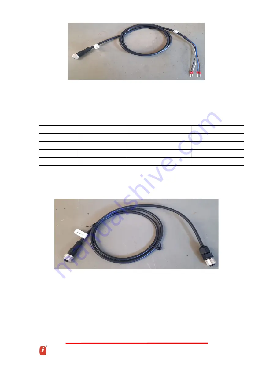
1.3.5. LOGSCDP1 CABLE FOR O OUTPUT FOR PRESSURE SENSOR
PINOUT P3
SEÑAL/SIGNAL
COLOR/COLOUR
SENSOR PIN
-
(- Vs)
MARRON / BROWN (8 cm)
1 (0V/S-)
+
(+ Vs)
BLANCO / WHITE (8 cm)
2 (VB)
A_V
S
AZUL / BLUE (8 cm)
3 (S+)
N.C.
-----
NEGRO / BLACK (8 cm)
---
CONNECTOR1
: 4-pole male with molded cable
CONNECTOR2:
4-pole female
LABEL1
:
iLOGS46CDO010
LABEL2
: SEÑAL/ COLOR/COLOUR


