User Manual
24
Flow Indicator Totaliser 1008S
REF NO: m18A/om/101
Issue No: 17
In above
example
Flow rate on
Display varies
between:
0
– 2000 for input of 0 % – 10%
2000
– 4000 for input of 10% – 50%
4000
– 4500 for input of 50 % – 60%
4500
– 7500for input of 60 % – 80%
7500
– 10000 for input of 80 % – 100%
If user wants a flow to be linear throughout the span than configure this parameter as:
SF1 = FS1, FL1 = 100 %.
User is not required to initialize SF2, SF3, SF4, SF5, FL2, FL3, FL4 and FL5.
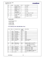
Pout Selection:
Pout value decides the pulse Output.
There will be a pulse at pulse output pins (PIN NO.9, PIN NO 10), whenever a integrated
total value is greater than by POUT by previous IT value [where last pulse is registered], it
will be added to the integration total value.
i.e.
Current IT value
≥ (Pout + previous IT value).
Example:
1
. If Flow rate = 1000, Pout = 1000, Time base = second,
Every second, 1000 is added in integration total. Since pout is 1000, 1 times of pout value
is added to integration-total every sec. Therefore we will have 1 pulse/sec.
2
. Flow rate = 1000, Pout = 100,
Time base = second,
Every second, 1000 is added in integration total. Since pout is 100, 10 times of pout value
is added to integration-total every sec. Therefore we will have 10pulses/sec. It could not
be observed on CRO. For this use a pulse counters for testing.
3.
Flow rate = 600, Pout = 10,
Time base = min,
Every second, 10(600/60) is added in integration total. Since pout is 10, 1 times of pout
value is added to integration-total every sec. Therefore we will have 1pulse/sec or 60
pulses/min.
4
. Flow rate = 600, Pout = 100,
Time base = min,
Every second, 10(600/60) is added in integration total. Since pout is 100, 1/10 times of
pout value is added to integration-
Total every sec. Therefore we will have 1 pulse/10 sec or 6 pulses/min.
Default Display:
This parameter will select the parameter to be displayed in run mode.
If Int tot / Bat tot is selected then in run mode „Integration total „/ „Batch total „will be
displayed on lower panel accordingly.
If
“
instrument type
” parameter is set as indicator, then this parameter will not be displayed
in Configuration mode and Integration total will be displayed in run mode.
N
o.
Flow
rate
Value
Param
eter
Display
Value
Input
Current
mA
1
FL1
10%
SF1
2000
5.6
2
FL2
50%
SF2
4000
12.0
3
FL3
60%
SF3
4500
13.6
4
FL4
80%
SF4
7500
16.8
5
FL5
100%
SF5
10000
20


