1.3
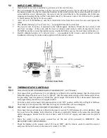
DISCONNECTING THE FLUE
1.
Shut off the gas supply at the valve behind the heater.
2.
Remove the access panel on the rear of the cabinet.
3.
Disconnect the gas line at the heater.
4.
Lift the flue sleeve about 75mm and support it with a wooden block.
5.
Slacken any flue clamp and lift the flue while moving the heater from beneath it.
6.
Slide the heater away from the wall, supporting the flue and trim on a suitable spacer.
7.
Keep the heater upright at all times to avoid displacing the logs.
1.4
REMOVING THE CABINET
1.
Remove the front panel (Baltimore only), the dress guard (if fitted), the louvre assembly and the glass (in
that order) as detailed in Section 1.1. For the Monaco, remove the bottom glass trim (one screw at each
end and three into the baseplate.
2.
Remove all access panels ( See Section 1.6.), the pedestal rear panel and the fan (if any).
3.
Disconnect the gas supply.
4.
Disconnect the flue, where applicable. See Section 1.3.
5.
Remove the control knob (STD models) and disconnect the Piezo lead from the bottom of the Piezo
(ACC and RMT models prior to December 2000).
6.
Remove the diverter hood from the rear of the cabinet.
7.
Withdraw the screws holding the rear panel of the cabinet to the heat exchanger.
8.
Extract all the screws under the bottom outer edge of the cabinet.
9.
Remove the screws inside the front of the firebox which fix the firebox sides to the cabinet.
10.
Remove any control rod(s).
11.
The cabinet can now be lifted straight up. Take care not to lose the bush in the control panel (STD
models).
1.5
REPLACING THE CABINET
1.
Lower the cabinet carefully over the firebox until it reaches the baseplate.
2.
Re-connect the Piezo lead (if fitted).
3.
Feed the control rod(s) up through the heat shield and the control panel (where applicable).
4.
Attach the lower end of the rod(s) at the valve (as required).
5.
Fit the bush on the control rod (STD models).
6.
Replace all the cabinet retaining screws, taking care not to over-tighten.
7.
Replace the screws holding the rear panel of the cabinet to the heat exchanger.
8.
Replace the diverter hood at the rear of the cabinet.
9.
Re-fit the control knob (STD models).
10.
Replace the glass, the louvre assembly, the dress guard (if fitted) and the Baltimore front panel. See
Section 1.2. Replace the Monaco front glass retainer, ensuring that the spacers are fitted on the end
fastening screws between the glass retainer and the side panel to allow easy fitting of the side access
panel.
11.
Re-assemble all access panels, the fan (if any) and the rear pedestal panel.
12.
Re-install the flue and gas supply and check for gas leaks.
1.6
ACCESS PANELS
1.6.1
REMOVING THE REAR ACCESS PANEL
1.
Remove four screws, three on the face and one underneath.
2.
Lift the panel clear.
1.6.2
REPLACING THE REAR ACCESS PANEL
1.
Offer the panel into position and re-fit the screws. Do not overtighten.
1.6.3
REMOVING THE SIDE ACCESS PANEL
1.
Remove two screws below the panel. In the case of the Monaco, the whole of the right hand side of the
cabinet is the access panel.
2.
Lift the panel gently upward, pulling the lower edge outward.
3.
Lower the panel until it is clear of the pins.
11
Summary of Contents for BALTIMORE MONACO NAPLES
Page 34: ...DRAWING 1 PILOT ASSEMBLIES ALSO MONACO ACC ALSO MONACO ECS 33 ...
Page 35: ...DRAWING 2 PLACEMENT OF EMBERS 34 ...
Page 36: ...DRAWING 4 GAS VALVES SEE 3 1 6 FOR NAPLES SEVILLE VALVE 35 ...
Page 38: ...DRAWING 7 LOG POSITIONING BALTIMORE MONACO NAPLES SEVILLE 37 ...
Page 39: ...DRAWING 8 REAR VIEW STANDARD MODELS 38 ...
Page 40: ...DRAWING 9 REAR VIEW ACC MODELS 39 ...
Page 41: ...DRAWING 10 REAR VIEW RMT MODELS 40 ...


