5.2
NAPLES AND SEVILLE
1.
Open the left lower louvre assembly to gain access to the control valve.
2.
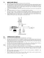
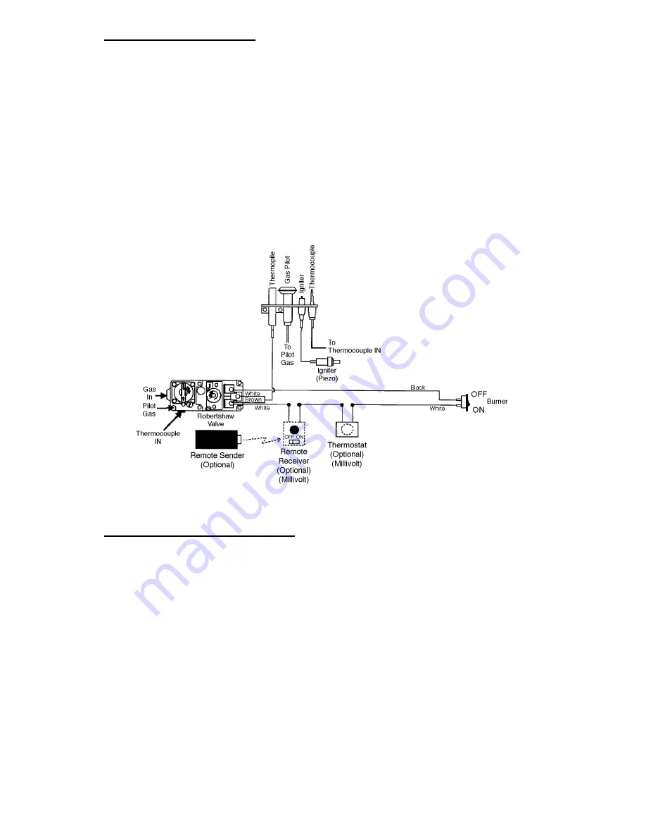
The two terminals on the front face of the valve are normally wired to the on/off switch on the side of
the fascia column. In order to retain the function of the on/off switch, the receiver should be wired in
series with this circuit. Alternatively, the receiver can be wired directly to the terminals, but in this case
stopping and starting the fire will be controlled entirely by the remote control. It will then not be possible
to start and stop the fire by the fascia switch.
3.
As in the case of the Baltimore, only the red and white wires from the receiver box are used. Ignore the
others.
6.
Fit 4 alkaline batteries (1.5 volt, size AA — not supplied) into the receiver unit.
7.
The receiver unit, in its box, is mounted on the wall alongside the fascia. Mount the box where it will
give best ‘coverage’ of the room, with the receiver window (and control switch) facing into the room.
Do NOT mount the receiver behind the louvres (inside the firebox case) as the heat there will destroy it.
8.
Install 2 alkaline batteries (1.5 volt, size AAA — not supplied) in the remote control and test run the
installation, following the instructions supplied with the remote control.
WIRING DIAGRAM
5.3
THERMOSTATIC CONTROLS
5.3.1
WALL-MOUNTED PROGRAMMABLE THERMOSTAT (ACC Models)
1.
First ensure that good batteries (3 x AA alkaline) are fitted in the wall thermostat, that the slide switch
behind the hinged bottom cover is set to ‘HEAT’, that the temperature setting on the thermostat is above
the prevailing room temperature, and that the pilot is alight. Full details of the wall-mounted thermostat
and programming instructions are supplied with it.
2.
Turn the control on the heater fully anticlockwise to the ‘ON’ position and the fire will light at full heat.
There may be a strong smell the first time the logs are fired but this will soon disappear.
5.3.2
THE IRRC 300 PORTABLE REMOTE THERMOSTAT (ACC Models)
1.
First check that good batteries are fitted in the remote control. To fit batteries (two AAA alkaline), slide
the cover below the display in the direction of the arrow and pull it further in the same direction firmly
until it disengages. Ensure that the receiver has a valid 230 volt AC supply, and make sure the pilot is
alight.
2.
Move the switch on the receiver control box (at the rear of the pedestal) to ‘REMOTE’. (See
RECEIVER SWITCH POSITIONS).
3.
Check the display on the remote control. If it reads ‘OFF’, aim the remote control toward the receiver
and press the centre button on the remote to switch it to ‘ON’.
25
Summary of Contents for BALTIMORE MONACO NAPLES
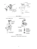
Page 34: ...DRAWING 1 PILOT ASSEMBLIES ALSO MONACO ACC ALSO MONACO ECS 33 ...
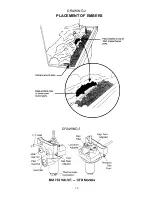
Page 35: ...DRAWING 2 PLACEMENT OF EMBERS 34 ...
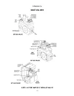
Page 36: ...DRAWING 4 GAS VALVES SEE 3 1 6 FOR NAPLES SEVILLE VALVE 35 ...
Page 38: ...DRAWING 7 LOG POSITIONING BALTIMORE MONACO NAPLES SEVILLE 37 ...
Page 39: ...DRAWING 8 REAR VIEW STANDARD MODELS 38 ...
Page 40: ...DRAWING 9 REAR VIEW ACC MODELS 39 ...
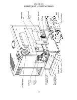
Page 41: ...DRAWING 10 REAR VIEW RMT MODELS 40 ...

