background image

7

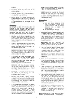
2.  Regularly check the condition of the engine air

cleaner, especially in dusty environments.

3.  The drive belt may stretch after a short period

of  use,  but  should  then  stabilise  for  a
considerable  time  if  not  overloaded  or
constantly slipped.
If the engine is not approximately level (i.e. if it
is  hanging  backwards  away  from  the  chute)
then  the  spring  pressure  on  the  belt  may  be
reduced causing the belt to slip.
To  return  the  engine  to  level:  Remove  the
belt guard; loosen the 4 engine mounting bolts
using  two  13mm  spanners;  raise  the  engine
mounting  plate  until  the  engine  is  tilting
slightly  forward;  pull  the  engine  back  in  its
mounting  slots  and  tighten  two  rear  engine
mounting  bolts; check  that  the  engine  is  now
level;  tighten  the  remaining  engine  bolts;
replace the belt guard.
NOTE:  Replace  the  drive  belt  when  the
engine  has  reached  the  end  of  its  slotted
holes and it is still sloping backwards.

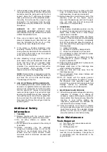
4.  If  the  engine  is  vibrating  badly,  the  10mm

engine pivot bolts  under the  engine mounting
plate  may  need  tightening.  Do  not  tighten
them fully, and after tightening check  that the
engine still pivots by lifting it by hand. If it does
not pivot, the belt will slip as the weight of the
engine  keeps  the  belt  tight.  Removing  the
pivot bolts and greasing them at least once  a
year will increase the life of the  pivot  bushes.
New  Nyloc  nuts  may  be  necessary  after
removing them a few times.

5.  To 

remove 

the 

chipper 

blade 

for

sharpening/replacement.


Disconnect  the  spark  plug  lead  from  the
spark plug.


Loosen 

the 

upper 

bolt 

on 

the

maintenance cover plate and remove  the
lower bolt.


Remove the plastic shredder chute.


Rotate  the  maintenance  cover  plate  to
expose the hole under the plate.


Rotate  the  shredder-chipper  rotor  until
the  chipper  blade  is  opposite  the
maintenance hole.


With  a  sharp  object  such  as  a  nail,
remove wooden debris from the allen key
holes  in  the  two  countersunk  chipper
blade bolts.


Remove  the  bolts  and  the  chipper  blade
using an allen key and a 13mm spanner.
[BEWARE  OF  THE  SHARP  EDGE  ON
THE CHIPPER BLADE.]


Sharpen  blade  to  45

o

.  Do  not  remove

more  than  2mm  of  material  as  this  will
cause  rotor  imbalance.  I.e.  the  minimum
blade dimensions are:


Never use a cracked chipper blade.


Use  new  Nyloc  nuts  when  replacing  the
chipper  blade,  and  new  bolts  if  they
appear  damaged.  Ensure  the  blade  is
sitting  flat  on  the  rotor  surface  before
tightening.


!

a)  4mm Allen key.
b)  8mm spanner.
c)  ¼” rod or a Phillips head screwdriver with

a shaft 6mm diameter or smaller.

d)  Bearing puller.
e)  Two 18mm open ended spanners.
f) 

1

/

8

” Allen key.

"

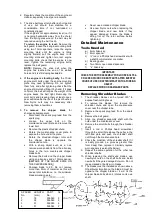
1.  The  shredder  blades  can  be  turned  180

o

  to

expose fresh cutting faces.

2.  To  remove  the  blades,  first  remove  the

shredder  chute  and  open  the  maintenance
cover near the chipper tube.

3.  Remove  the  spark  plug  lead  from  the  spark

plug.

4.  Remove the belt guard.
5.  Align  one  shredder  assembly  shaft  with  the

hole under the maintenance cover.

6.  Remove the  small  bolts  through the  shredder

shaft.

7.  Insert  a  rod  or  Phillips  head  screwdriver

through the small hole above the pulley in the
left  hand  plate  and  push  the  shredder  shaft
out through the maintenance hole.

8.  Check the condition of the shredder shaft. If it

is  badly  grooved  (i.e.  grooves  greater  than
1mm  deep)  then  replace  it.  Similarly  replace
worn spacers (see lengths below.)

9.  Repeat  the  same  operation  for  the  other  two

shredder shafts.

10.  When  replacing  the  shafts  and  blades,  use

new  Nyloc  nuts  on  the  shaft  bolts  and  install
new bolts if they are damaged or worn. Do not
reuse cracked or badly worn blades.

11.  The blades must be installed as shown above.

Of particular importance, the blade X must be
opposite  the  chipper  blade  or  it  will  hit  the
chipper blade bolts when it rotates on its own
shaft.

IMPORTANT:

CHECK THE ROTOR ASSEMBLY FOR LOOSE BOLTS &

CRACKED, WORN OR BENT PARTS AFTER EVERY 20
HOURS OF USE OR AFTER IMPACT WITH A FOREIGN

OBJECT.

REPLACE WORN OR DAMAGED PARTS.

SPACER
No.

LENGTH
(mm)

PART
No.

No. PER

1

18

536043

2

2

36

536042

2

3

51

536045

4

4

51

536044

2

Summary of Contents for Petrol Chipper Shredder

Page 1: ...Please read these instructions carefully before assembly Keep the instructions in a safe place for future use Owner s Manual Chipper Shredder www masport com 536128 ...

Page 2: ...ENGLISH ...

Page 3: ...ic Page Topic Page Initial Assembly 3 Basic Maintenance Information 6 Operating Instructions Detailed Maintenance Information Transporting 3 Removing Shredder Blades 7 Preparation Starting 4 Engine Removal Rotor Removal 8 Chipping 5 Belt Replacement 8 Shredding 5 Warning Decals 9 Additional Safety Information Training 6 Operation 6 Maintenance Storage 6 ...

Page 4: ...s Then put the two axle clips on the ends of the axle 5 Lift the engine and remove the wooden packer that is under the engine mounting plate 6 Attach the handle to the shredder chute 7 Attach the shredder chute to the chassis using two 8mm x 20mm screws and two chute retainers with plain washers and spring washers on the screws at the front and with two Nyloc nuts outside the chute at the sides Se...

Page 5: ...e explosive a Use only an approved container for fuel b Never remove fuel cap or add fuel with engine running Allow engine to cool before refueling Do not smoke c Never refuel the machine indoors d Never store the machine or fuel container inside where there is an open flame such as a water heater 1 Ensure the Chipper Shredder is on stable level ground so it won t tip over Do not operate the machi...

Page 6: ...wards with the spark plug disconnected and prising the material out of the tube with a long knife screwdriver etc NOTE DO NOT continue chipping if the drive belt is slipping or smoking To readjust the belt see maintenance information NEVER operate the machine with the small maintenance cover plate in its open position or removed Serious injury would result if someone put their finger into the hole...

Page 7: ...onoxide which is colourless odourless and tasteless 1 5 Do not place hands or any other part of the body or clothing inside the feeding chutes discharge area or near any moving part 1 6 Before inspecting or servicing any part of the machine shut off the power source disconnect the spark plug wire from the spark plug and make sure that all moving parts have come to a complete stop 2 OPERATION 2 1 W...

Page 8: ...ntersunk chipper blade bolts Remove the bolts and the chipper blade using an allen key and a 13mm spanner BEWARE OF THE SHARP EDGE ON THE CHIPPER BLADE Sharpen blade to 45 o Do not remove more than 2mm of material as this will cause rotor imbalance I e the minimum blade dimensions are Never use a cracked chipper blade Use new Nyloc nuts when replacing the chipper blade and new bolts if they appear...

Page 9: ...clip is fitted 1 Remove the belt guard 2 Disconnect the spark plug lead from the spark plug 3 Loosen the four engine mounting bolts and slide the engine forward 4 Raise the engine and remove the belt 5 When a new belt is installed readjust the engine position so that it is level when the belt is tight 6 Attach the belt guard Micro Switch Adjustment If the m c will not start check that the chipper ...

Page 10: ...9 Masport Chipper shredders are manufactured in New Zealand by MASPORT LTD 1 37 MT WELLINGTON HIGHWAY P O Box 14 349 Panmure Auckland New Zealand Revised Sept 2004 ...

Page 11: ...Español ...

Page 12: ...uradora Masport Para una información en el futuro por favor rellene la tabla siguiente Nº Serie Revendedor Fecha de compra INDICE PAGINA MONTAJE INICIAL 3 TRANSPORTE 3 PREPARACIÓN PARA ARRANQUE 4 TRITURAR TRONCOS 5 TRITURAR RAMAS 5 PREPARACIÓN 6 ARRANQUE 6 MANTENIMIENTO Y ALMACENAJE 6 MANTENIMIENTO BASICO 6 SUSTITUCIÓN DE CUCHILLAS 7 AJUSTE MOTOR 8 SUSTITUCIÓN CORREA 8 SEÑALES ADVERTENCIA 9 ...

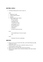
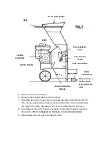
Page 13: ...sadores 4 tornillos 30 mm para las asas Caja 2 Tolva de plástico para ramas con su goma Asas Caja 3 Tolva para troncos con su abrazadera MONTAJE 1 Prepare un trozo de tronco de 95 x 95 x 300 y posiciónelo debajo de la salida de descarga Ver Fig 1 2 Ponga las dos patas en forma de L en posición correcta junto con sus correspondiente tornillos y apriete 3 Sitúe el tronco en la otra parte de la máqui...

Page 14: ... las asas sobre la tolva de ramas 7 Ensamblar la tolva de ramas sobre la maquina usando los dos tornillos 8 x 20 mm y las dos sujeciones para tolva coloque los tornillos con la arandela plana por dentro de la tolva y las tuercas de freno a la parte exterior Ver Fig 2 8 Ensamble la tolva de troncos sobre la salida circular de la maquina y ajuste la abrazadera Nota la maquina no arrancara si no cone...

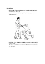
Page 15: ...ed deslizándola sobre las ruedas PELIGRO NUNCA DESPLACE LA MAQUINA CON EL MOTOR EN FUNCIONAMIENTO 2 En terrenos difíciles mantenga firmemente agarradas las asas de la maquina para no volcarla 3 Recuerde rellenar primero el cárter de aceite del motor y luego posicionar la tolva de troncos ...

Page 16: ...úrese antes de arrancar la máquina de que los tornillos tuercas y otros componentes estén bien ajustados y apretados Sustituya cualquier pieza que observe defectuosa o dañada antes de la puesta en marcha 4 Mantenga especial atención con los combustibles y sus gases ya que estos son especialmente explosivos Utilice solo el combustible para rellenar el depósito de combustible del motor Nunca abra el...

Page 17: ...mente la maquina y su funcionamiento TRITURADO DE TRONCOS IMPORTANTE NUNCA PONGA SUS MANOS O DEDOS EN LA TOLVA PARA TRONCOS Y PARA PROTENCCIÓN DE OTROS NO DEJE NUNCA LA MAQUINA DESATENDIDA CUANDO ESTE TRABAJANDO LA MAQUINA NUNCA ARRANCARÁ SI NO ESTA SITUADA LA TOLVA PARA TRONCOS 1 Podrán triturarse troncos con un diámetro máximo de 65 mm los troncos de menor diámetro se trituraran mas fácilmente N...

Page 18: ...as ramas o arbustos B Utilice siempre protección visual o gafas 1 Materiales orgánicos así como ramas pueden ser trituradas con la trituradora Vid o parras se recomienda que no superen los 300 mm de longitud ya que estos podrían enrollarse en el eje y dañar la mano del operario IMPORTANTE NUNCA INTENTE TRITURAR MATERIALES COMO VIDRIO METAL BOTELLAS DE PLÁSTICO O PIEDRAS 2 Se recomienda el uso de g...

Page 19: ...ste una criba especial la cual nos proporcionara un mejor funcionamiento Para la sustitución de esta debe quitar el pasador en forma de R quitar el eje de ambos lados y sustituir la criba en la misma posición que quito la antigua SEGURIDAD ADICIONAL 1 PREPARACIÓN 1 1 Familiarícese con el manual antes de empezar a trabajar 1 2 No permita que los niños trabajen con este equipo 1 3 No trabaje cerca d...

Page 20: ...re totalmente frio 3 2 Almacene la maquina fuera del alcance de los niños asegúrese de que el depósito de combustible este vacío y que la maquina se encuentra fuera del alcance de cualquier llama MANTENIMIENTO BASICO LLAVES REQUERIDAS a 2 llaves de 13 planas b Llave allen 5 mm c 1 llave de 10 mm 1 De 5 10 h de uso compruebe el nivel de aceite y rellénelo en caso de ser necesario Cambie el aceite d...

Page 21: ...ra realizar esta operación se recomienda que se dirija al servicio post venta donde adquirió la maquina esta operación debe ser supervisada por un profesional Sustitución del motor Afloje los 4 tornillos del motor retire la correa de transmisión desconecte el muelle de tensión y finalmente retire el motor Sustitución del tambor de cuchillas Para realizar esta operación se recomienda que se dirija ...

Page 22: ...cionamiento es correcto 3 En caso de no escuchar el click significa que el interruptor no esta actuando en la posición correcta entonces afloje las tuercas 3 y 4 4 Mueva el interruptor hasta que escuche un click entonces reajuste las tuercas 3 y 4 5 Para asegurarse de que ahora el funcionamiento ya es correcto saque la tolva e introduzquela seguidamente si escucha el click significa que ya funcion...

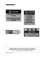
Page 23: ... DIAMETRO SUPERIOR A 15 MM PELIGRO SISTEMA DE CORTE DE CUCHILLAS MANTENGA MANOS Y PIES FUERA DE LA ZONA DE DESCARGA PELIGRO SISTEMA DE CORTE DE CUCHILLAS MANTENGA LAS MANOS FUERA DE LA TOLVA DE TRONCOS ADVERTENCIA LEA DETENIDAMENTE EL MANUAL DE INSTRUCCIONES MANTENGASE A UNA DISTANCIA PRUDENCIAL QUITE LA PIPA DEL MOTOR ANTES DE REALIZAR CUALQUIER OPERACIÓN CON LAS CUCHILLAS ...

Page 24: ......

Reviews: