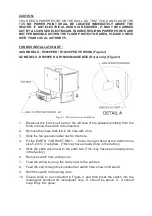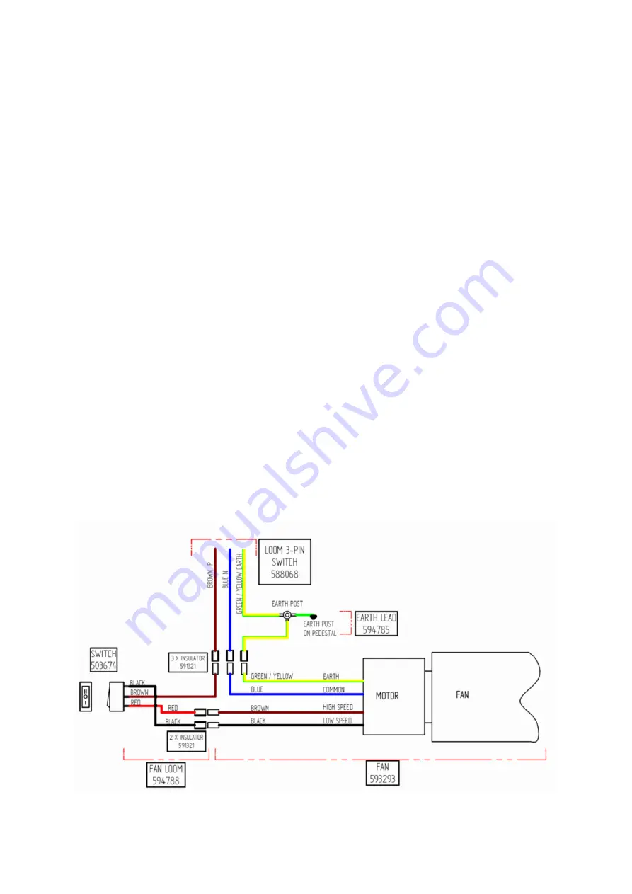
Circuit Diagram (Figure 6)
Figure 6. Circuit Diagram
—
Revision A (Prior to Nov 2013)
The circuit diagram is shown as follows in Figure 6.
5.
Remove switch from wiring loom.
6.
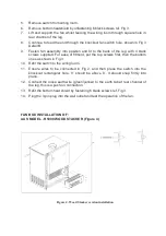
Mount the fan assembly at the rear of firebox using 4 screws as shown in
Figure 5.
7.
Feed the end of the loom trough knockout fan switch hole, shown in Fig 5
8.
Refit the switch to the wiring loom.
9.
Ensure switch wires are connected as shown in Fig 2, and then press the
switch into the knockout rectangular hole, ‘II’ should be above ‘0’. It should
snap firmly into place.
10.
Screw switch bracket in place. Endure all cables are tucked properly as
shown in Fig 5 i.e. gap between side panel and the inner side panel.
11.
Connect the loose earth wire (green) to the rivet tab at rear panel , this is a
push
-
on connection.
12.
Plug the 3
-
pin plug into the wall outlet and test the operation of the fan.


