background image

5

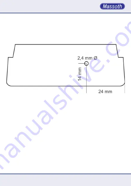
Durchmesser und Bohren Sie vorsichtig 

das Loch. Setzen Sie anschließend die 

Rückseite des Gehäuses wieder auf, 

dabei das Funksenderkabel durch das 

soeben gebohrte Loch stecken. Schrau-

ben Sie das Gehäuse zu.

3. Technische Daten

Spannungsversorgung: 3,3 V vom 

Navigator

Stromaufnahme: Max. 50mA

Sendeleistung: 9,8 mW 

Betriebstemperatur: -20 .. 70° C 

Hinweis zur Temperatur: Um Kondens-

wasserbildung zu vermeiden, benutzen 

Sie die Elektronik bei Temperaturen 

unter 0°C nur, wenn diese  vorher aus 

einem beheizten Raum kommt. Die 

Wärme die während des Fahrbetriebs 

erzeugt wird, reicht aus um Kondens-

wasserbildung zu verhindern.

ing the antenna through the hole and 

fasten the screws.

3. Technical specifications

Power supply: 3,3 V from navigator

Power input: Max. 50mA

Transmitter power: 9,8 mW

Temperature range: -4° F .. 158° F 


Note regarding the operating tem-

perature: to prevent the production of 

condensed water, use the Multi-RC 

Module in freezing conditions only if 

it was previously stored in a heated 

environment. The heat produced dur-

ing operation is sufficient to prevent 

condensed water.

Abbildung 3: Bearbeitung Gehäuseunterschale

Illustration #3: Processing backplane

Summary of Contents for DiMAX 8133301

Page 1: ...DiMAX Funksender DiMAX RC Sender Art Nr Item No 8133301 Version 1 0 ...

Page 2: ...isplay Rechts unterhalb des Displays befindet sich der Sockel mit 10 Stiften zur Aufnahme des Funkmoduls 1 General Information The DiMAX RC Sender extends the DiMAX Navigator with radio control The technology allows bidirectional outdoor use with ranges of appr 320 feet Even inside and between buildings a radio range of 320 feet can be reached The Navigator requires a minimum firmware of version 1...

Page 3: ...ers eingesteckt sind Ist der Sender nicht korrekt eingesteckt führt dies zu irrepa rablen Schäden an der Elektronik nector as shown in the drawing above Make sure that all ten pins are con nected correctly If not this may cause irreparable damage to the electronics After installation take the back cover assemble the casing and screw in the five screws Abbildung 1 Öffnen der Rückwand Illustration 1...

Page 4: ...nd Nehmen Sie einen handelsüblichen Bohrer mit 2 4 mm Illustration 3 shows the drilling instructions for the rear cover of the Navigator Mark the location for drilling with a pointy tool and carefully drill a hole with a regular 2 4mm drill bit Then put the rear cover back in place insert Abbildung 2 Einbau des Funksenders Illustration 2 Assembling the RC sender ...

Page 5: ...er aus einem beheizten Raum kommt Die Wärme die während des Fahrbetriebs erzeugt wird reicht aus um Kondens wasserbildung zu verhindern ing the antenna through the hole and fasten the screws 3 Technical specifications Power supply 3 3 V from navigator Power input Max 50mA Transmitter power 9 8 mW Temperature range 4 F 158 F Note regarding the operating tem perature to prevent the production of con...

Page 6: ... Internetseite finden Sie die jeweils aktuellen Broschüren Produktinformationen Dokumenta tion und Softwareprodukte rund um MASSOTH Produkte 3 1 Warranty Service Support MASSOTH warrants this product against defects in materials and workmanship for one year from the original date of purchase Other countries might have different legal warranty situations Normal wear and tear consumer modifications ...

Page 7: ...7 hotline massoth com Dieses Produkt entspricht den CE Konformitätsrichtlinien für elektrische Klein geräte in der aktuellen Fassung This unit conforms to the CE Standards RoHS Dieses Produkt ist nach den aktuellen EG Richtlinien umgangssprachlich blei frei hergestellt und damit RoHS konform This unit is manufactured according to the latest EG Standards for lead free manufacturing conforming to Ro...

Page 8: ...MADE IN GERMANY 8133301_0510_ML Massoth Elektronik GmbH Frankensteiner Str 28 D 64342 Seeheim Germany FON 49 0 6151 35077 0 FAX 49 0 6151 35077 44 eMail info massoth de www massoth de ...

Reviews: