background image

08

07

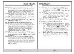
5.5.2 Pull the trigger on the sensor and wait the sensor 
          to be switched to the measuring mode, and then
          gently touch “SEL” key on the sensor twice. The
          emissivity symbol “EMS” will be shown on LCD, 
          together with the value of emissivity E=1.00. 
5.5.3 Gently touch the “

”key on the panel to increase

          the emissivity value as shown on display; Press 
          the “

” key to decrease it. 

5.5.4 After the above setup is complete, press “MODE”
          to confirm the value of emissivity. 
5.5.5 The effective setup range for radiation: “EMS” is 
          between 0.10 and 1.00. 

5.6 Temperature Limit Alarming Function 

5.6.1 Pull the trigger on the sensor, and gently touch 
          “SEL” key on the left panel consecutively for three
          times, and then “HAL” symbol and “1000” are 
          shown on display, and the sensor is switched to 
          the mode for setting the upper limit alarming.
          Gently touch “

”or “

” to adjust the upper 

          temperature limit alarming value.
5.6.2 After the value is set, gently touch “MEM” key on
          the panel to turn on/off the alarming mode. When
          under “alarming on” mode, “ 

” symbol is shown 

          on display.
5.6.3 Pull the trigger on the sensor, and gently touch 
          “SEL” key on the left panel consecutively for four
          times, and then “LAL” symbol and “00” are shown
          on display, and the sensor is switched to the mode
          for setting the lower limit alarming. Gently touch 
          “

”or “

”to adjust the lower temperature limit

          alarming value.

HIB 

5.6.5 When the sensor detects that the surface 
          temperature of an object is higher or lower than
          the preset alarming value, it will give off “doo-doo”
          alarming sound, in the mean time “HAL” or “LAL” 
          symbol will flash on display.  

Under the attached probe measuring mode, the 
upper/lower limit alarming function is deactivated. 

5.7 Settings For Auto Measurement 

5.7.1 Pull the trigger on the sensor and wait the sensor
          to be switched to measuring mode, and then gently
          touch “ USB ” key on the left side of the sensor for
          a short moment to shown “ 

” symbol on LCD; 

          Then, press “SEL” key for 3 seconds and the 
          “SCAN” symbol on LCD stops flashing. Release 
          the trigger, and the sensor is switched to the mode 
          of auto measuring.
5.7.2 Under the mode of auto measuring, gently touch
          the “USB” key on the left side of the sensor for a 
          short moment, and the mode of auto measuring 
          is switched off. 

USB 

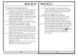
5.6.4 After the value is set, gently touch “MEM” key on 
          the panel to turn on/off the alarming mode. When 
          under “alarming on” mode, “ 

” symbol is shown 

          on display. 

LOB 

Summary of Contents for MS6550A

Page 1: ...MS6550A Infrared Thermometer User Manual 40 20 MEM USB RCL SEL 80 S Unit mm Range 32 C 1200 C MS6550A INFRARED THERMOMETER D 4000 2000 1000 D S 50 1 ...

Page 2: ... 5 5 Emissivity Settings 6 5 6 Temperature Limit Alarming Function 7 CONTENTS 5 8 Save Recall Delete A Record 9 6 Distance To Object Size Ratio D S 11 7 Emissivity 12 8 Maintenance 13 8 1 Battery Replacement 13 8 2 Lens Cleaning 14 8 3 Housing Cleaning 14 9 Technical Specifications 14 10 Accessories 15 5 4 Connect the Temperature Probe 5 5 7 Settings For Auto Measurement 8 5 9 AC Power USB Communi...

Page 3: ...on Please check the housing of the temperature sensor before using Never use a damaged sensor Check for any damage or any missing plastic rubber part 01 The battery should be replaced immediately in case the battery indictor is shown on display In case the temperature sensor does not function well please stop using it The protecting device of the sensor may have been damaged If it appears to have ...

Page 4: ... 1 and Figure 1 Symbol Symbol High voltage hazard Danger level is higher than that of CAUTION label Caution Laser Conforms with requirements of EU and EFTA Danger Table 1 Symbols 03 A LCD B Laser key C Mode selection key D Backlight key E C F toggle key F Function selection key G Save key H Recall Data key I USB Communication key J Trigger K Aiming device L Battery cover M USB communication port N...

Page 5: ...it 5 3 View Max Min Ave Diff Temperature 5 4 1 When using K type probe for measuring temperature please do properly insert the K type probe into the K type standard temperature base at the lower part of the sensor 5 4 2 Pull the trigger on the sensor wait for the sensor to be switched into the measuring mode and then gently touch SEL key on the sensor for a short moment The sensor will then be swi...

Page 6: ...touch SEL key on the left panel consecutively for four times and then LAL symbol and 00 are shown on display and the sensor is switched to the mode for setting the lower limit alarming Gently touch or to adjust the lower temperature limit alarming value HIB 5 6 5 When the sensor detects that the surface temperature of an object is higher or lower than the preset alarming value it will give off doo...

Page 7: ... power supplier can power the temperature sensor to perform measurements for a long period of time For your safety please use the power supplier provided by our company 5 9 2 To use the function of USB communication firstly install the communication software from CD then insert the USB data cable to PC and the sensor and then pull the trigger Gently touch USB key on the left side of the sensor so ...

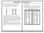
Page 8: ...tion from objects other than the test object it is advisable to carry out measurements in a distance shorter than what is calculated according to D S 7 Emissivity Emissivity is a measure of the radiation energy of the corresponding material This temperature sensor allows you to adjust the emissivity of the sensor according to the type of the test surface Please refer to Table 2 Table 2 Surface Emi...

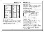
Page 9: ...cations Temperature range for infrared measurement Temperature Range Model 32 to 1200 ºC 25 to 2192 ºF Accuracy 510 ºC 1 5 of the reading 50 510 ºC 1 5 of the reading 1ºC 15 50 ºC 1 5 of the reading 2ºC 32 15 ºC 3 ºC Repeat error 0 5 of the reading or 0 5 ºC 8 2 Lens Cleaning Firstly use clean compressed air to blow off any small particles on the lens surface and then use a damp cotton swab to car...

Page 10: ...e 9V battery Ambient temperature 10 to 50 ºC Ambient Humidity 10 to 90 RH at 30 ºC Storage temperature 20 to 50 ºC without battery Dimensions Length 140 56 190 Weight 500g 10 Accessories Standard Accessories Instruction Manual 1 Standard K type thermo couple 40 to 260 ºC 1 USB data cable 1 Data communication software CD 1 Leather bag 1 9V battery 6F22 1 Optional Accessories DC 9V power supply 7101...

Reviews: