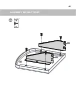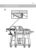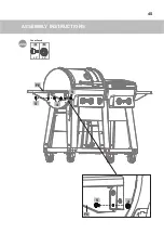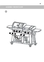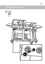
ASSEMBLY INSTRUCTIONS
56
31
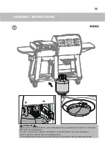
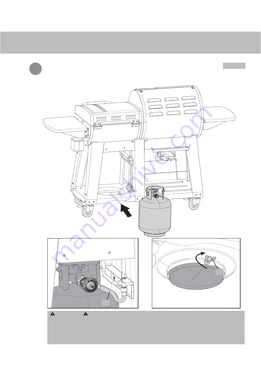
ATTENTION
• FOR YOUR SAFETY, DO NOT ATTEMPT TO LIGHT THIS BARBECUE UNTIL YOU HAVE REVIEWED PAGES 4-8 OF THE MASTER
CHEF® SAFETY AND CARE MANUAL.
• ALL SAFETY AND LEAK TESTS MUST BE PERFORMED BY THE END USER, PRIOR TO LIGHTING THIS BARBECUE.
• DO NOT STORE EXTRA PROPANE TANKS WITHIN BARBECUE CART.
• IF THE BURNER DOES NOT IGNITE, ADJUST THE POSITION OF THE ELECTRODE SET OR ELECTRONIC IGNITION WIRE.
Back View
EE
DP
Summary of Contents for 399-8532-8
Page 6: ...ASSEMBLY INSTRUCTIONS 6 1 x 8 2 DQ DQ DO You will need Front View ...
Page 7: ...ASSEMBLY INSTRUCTIONS 7 2 DO DA x 3 2 Front View You will need Do not tighten screws ...
Page 8: ...ASSEMBLY INSTRUCTIONS 8 3 DO DB x 3 2 Front View You will need Do not tighten screws ...
Page 9: ...ASSEMBLY INSTRUCTIONS 9 4 DO DE x 2 2 Front View You will need Do not tighten screws ...
Page 10: ...ASSEMBLY INSTRUCTIONS 10 5 DO DC Back View x 3 2 You will need Do not tighten screws ...
Page 11: ...ASSEMBLY INSTRUCTIONS 11 6 DO DD x 3 2 Back View You will need Do not tighten screws ...
Page 12: ...ASSEMBLY INSTRUCTIONS 12 7 DO DF Back View x 2 2 You will need Do not tighten screws ...
Page 13: ...ASSEMBLY INSTRUCTIONS 13 8A DO DA Back View DE x 4 3 You will need ...
Page 14: ...ASSEMBLY INSTRUCTIONS 14 8B DO DA Back View DE DG Tighten the screws ...
Page 15: ...ASSEMBLY INSTRUCTIONS 15 DO Back View DB DG 9A x 4 3 You will need ...
Page 16: ...ASSEMBLY INSTRUCTIONS 16 9B DO DB Back View DE DH Tighten the screws ...
Page 17: ...ASSEMBLY INSTRUCTIONS 17 10A DO DF DC Front View x 4 3 You will need ...
Page 18: ...ASSEMBLY INSTRUCTIONS 18 Tighten the screws 10B DO DC DI DF Front View ...
Page 19: ...ASSEMBLY INSTRUCTIONS 19 DO DF DD 11A x 4 3 Front View You will need ...
Page 20: ...ASSEMBLY INSTRUCTIONS 20 DO DJ DF DD 11B Tighten the screws Front View ...
Page 21: ...ASSEMBLY INSTRUCTIONS 21 12A DO Back View DE DF x 4 3 You will need ...
Page 23: ...ASSEMBLY INSTRUCTIONS 23 13 Back View DN DE x 4 3 You will need DN DH DN DJ ...
Page 24: ...ASSEMBLY INSTRUCTIONS 24 14 DA Back View DE DC DM DF x 2 3 You will need DM DM DA DM 1st 2nd ...
Page 25: ...ASSEMBLY INSTRUCTIONS 25 15 Back View BK BJ DI x 4 3 You will need DG BK DI BK ...
Page 27: ...ASSEMBLY INSTRUCTIONS 27 16B x 4 x 4 1 9 You will need 1 9 8 BA 1 9 8 BA x 4 8 ...
Page 28: ...ASSEMBLY INSTRUCTIONS 28 16C AF AG AH 7 7 6 AG 6 x 2 x 2 6 7 You will need ...
Page 29: ...ASSEMBLY INSTRUCTIONS 29 17A CA CF EL You will need CB ...
Page 30: ...ASSEMBLY INSTRUCTIONS 30 x 4 x 4 1 9 1 9 8 CB 1 9 8 CB You will need 17B x 4 8 ...
Page 32: ...ASSEMBLY INSTRUCTIONS 32 17D x 5 x 5 3 10 You will need CB 10 3 2nd 1st ...
Page 33: ...ASSEMBLY INSTRUCTIONS 33 17E AM 6 AG 6 AG 7 7 x 2 x 2 6 7 You will need ...
Page 34: ...ASSEMBLY INSTRUCTIONS 34 18 ED 1st 2nd DK ED x 1 12 You will need ...
Page 35: ...ASSEMBLY INSTRUCTIONS 35 19A CB CH x 2 3 You will need CB CH ...
Page 36: ...ASSEMBLY INSTRUCTIONS 36 19B CG CB x 2 x 2 3 10 CG 10 3 You will need ...
Page 37: ...ASSEMBLY INSTRUCTIONS 37 20 FA x 2 FB x 2 x 4 x 4 4 5 You will need ...
Page 38: ...ASSEMBLY INSTRUCTIONS 38 21A FE FC FD x 4 2 You will need ...
Page 39: ...ASSEMBLY INSTRUCTIONS 39 21B FB FA FB x 4 2 You will need ...
Page 40: ...ASSEMBLY INSTRUCTIONS 40 21C FE FC ...
Page 41: ...ASSEMBLY INSTRUCTIONS 41 x 2 x 2 4 5 You will need 21D FE FD 5 4 5 5 4 ...
Page 42: ...ASSEMBLY INSTRUCTIONS 42 22A FE FC FD x 4 2 You will need ...
Page 43: ...ASSEMBLY INSTRUCTIONS 43 22B FA FB x 4 2 You will need FA ...
Page 44: ...ASSEMBLY INSTRUCTIONS 44 22C BA FE FD ...
Page 45: ...ASSEMBLY INSTRUCTIONS 45 22D x 2 x 2 4 5 You will need FC 5 4 FE 5 5 4 ...
Page 46: ...ASSEMBLY INSTRUCTIONS 46 23 EG ...
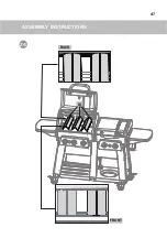
Page 47: ...ASSEMBLY INSTRUCTIONS 47 24 BI BACK FRONT ...
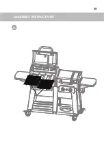
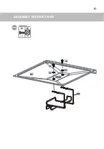
Page 48: ...ASSEMBLY INSTRUCTIONS 48 25 BG ...
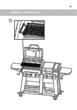
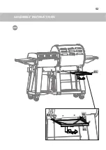
Page 49: ...ASSEMBLY INSTRUCTIONS 49 26 BH ...
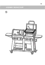
Page 50: ...ASSEMBLY INSTRUCTIONS 50 27 CA ...
Page 51: ...ASSEMBLY INSTRUCTIONS 51 28A 3 3 11 11 BL BM x 2 x 2 3 11 You will need ...
Page 52: ...ASSEMBLY INSTRUCTIONS 52 28B BL BK BJ BJ BL BK ...
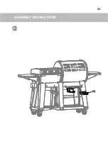
Page 53: ...ASSEMBLY INSTRUCTIONS 53 28C BN ...
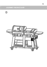
Page 54: ...ASSEMBLY INSTRUCTIONS 54 29 CI ...
Page 55: ...ASSEMBLY INSTRUCTIONS 55 30 x 2 13 You will need ...
Page 59: ...59 ...

