background image

PROPOSITION 65 WARNING

Some dust created by using power tools contain chemicals
known  to  the  state  of  California  to  cause  cancer,  birth
defects  or  other  reproductive  harm.  Some  examples  of
these chemicals are:

• Lead from lead-based paints.
• Crystalline  silica  from  bricks  and  cement  and  other
   masonry products, and
• Arsenic and chromium from chemically treated lumber.

Your risk from these exposures varies depending on how
often you do this type of work. To reduce your exposure to
these chemicals: work in a well ventilated area and work
with approved safety equipment, such as dust masks that
are specially designed to filter out microscopic particles.

Avoid prolonged contact with dust from power sanding,
sawing, grinding, drilling, and other construction activities.
Wear protective clothing and wash exposed areas with soap
and water. Allowing dust to get into your mouth or eyes or
to  lie  on  the  skin  may  promote  absorption  of  harmful
chemicals.

Safety is a combination of using common sense, staying
alert,  and  knowing  how  your  miter  saw  works.  Read
this manual to understand this miter saw and how to use it
safely.

GENERAL SAFETY IMFORMATION

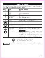
• 

Keep guards in place and in working order.

• 

Remove adjusting keys and wrenches.

 Form a habit of

   checking  to  see  that  keys  and  adjusting  wrenches
   are removed from the tool before turning it on.
• 

Keep the work area clean.

 Cluttered areas and benches

   invite accidents.
• 

Don’t use in a dangerous environment.

 Don’t use power

   tools in damp or wet locations or expose them to rain.
   Keep the work area well lit.
• 

Keep children away.

 All visitors should be kept at a safe

   distance from the work area.
• 

Make the workshop childproof

 with padlocks and master

   switches or by removing starter keys.
• 

Don’t force the tool;

 It will do the job better and more

   safely  when  used  at  the  rate  at  which  it  is  designed
   to work.
• 

Use the right tool.

 Don’t force a tool or attachment to do

   a job that it was not designed to do.
• 

Use the proper extension cord.

 Make sure your extension

   cord is in good condition. Use only a cord heavy enough
   to carry the current your product will draw. An undersized
   cord will cause a drop in line voltage resulting in loss of
   power and overheating. A wire gauge size (A.W.G.) of at
   least 14 is recommended for an extension cord 25 feet or
   less in length. If in doubt, use the next heavier gauge. The
   smaller the gauge number, the heavier the cord.

GENERAL SAFETY RULES

SAFETY INSTRUCTIONS

Page 4


WARNING:


Read and understand all instructions.

Failure to follow all instructions listed below, may result in
electric shock, fire and/or serious personal injury. Save all
warnings and instructions for future reference.


WARNING:


The use of this tool can generate and/

or disburse dust, which may cause serious and permanent
respiratory or other injury. Always use protection appropriate
for the dust exposure. Direct particles away from the face
and body.


WARNING:


To  avoid  the  risk  of  personal  injury,

do  not  modify  this  power  tool  or  use  accessories  not
recommended to fit your tool.


WARNING:


Read warnings and conditions about

your carbide tipped saw blade.
• Do  not  operate  the  saw  without  the  proper  saw  blade
   guard in place.
• Carbide is a very hard but brittle material. Care should be
   taken while mounting, using and storing carbide tipped
   blades to prevent accidental damage.
• Slight  shocks,  such  as  striking  the  tip,  can  seriously
   damage  the  blade.  Foreign  objects  on  the  work  piece,
   such as wire or nails, can also cause tips to crack or break
   off.
• Before using, always visually examine the blade and tips
   for  cracks,  breakage,  missing  or  loose  tips,  or  other
   damage.
• Do not use if damage is suspected. Failure to heed safety
   instructions  and  warnings  can  result  in  serious  bodily
   injury or loss of eyesight.


CAUTION:


Always     follow     proper     operating

procedures  as  defined  in  this  manual  —  even  if  you
are familiar with use of this or similar tools. Remember that
being careless for even a fraction of a second can result in
severe personal injury.

Handling the power cord on this product may expose you
to  chemicals  known  to  the  State  of  California  to  cause
cancer and birth defects or other reproductive harm. Wash
hands after handling.

Summary of Contents for 240-0028

Page 1: ...R S MANUAL CAUTION To Reduce The Risk Of Injury User Must Read And Understand Operator s Manual Save These Instructions For Future Reference For questions comments technical assistance or repair parts...

Page 2: ...afety Symbols Safety Instructions Overview Specifications Contents Assembly Adjustment Operation Maintenance Troubleshooting Warranty Page 2 Page 3 Page 10 Page 11 Page 12 Page 13 Page 21 Page 26 Page...

Page 3: ...use eye protection which is marked to comply with ANSI Z87 1 Symbol Name Designation Explanation V Volts Voltage A Amperes Current Hz Hertz Frequency cycles per second W Watts Power Alternating curren...

Page 4: ...re using this tool Failure to follow all instructions listed below may result in electric shock fire and or serious personal injury WARNING Indicates a potentially hazardous situation which if not avo...

Page 5: ...your extension cord is in good condition Use only a cord heavy enough to carry the current your product will draw An undersized cord will cause a drop in line voltage resulting in loss of power and ov...

Page 6: ...icing the saw Do not expose to rain or use in a damp location When servicing use only identical replacement parts Never reach around the saw blade Do not perform any operation freehand Always place th...

Page 7: ...wear safety goggles or safety glasses with a side shield and a full face shield when needed We recommend a Wide Vision Safety Mask for use over eyeglasses or standard safety glasses with side shields...

Page 8: ...ber tools or other obstructions while you are working with a power tool Failure to do so can result in serious personal injury WARNING Check extension cords before each use If damaged replace immediat...

Page 9: ...e saw blade from turning Depress and hold the lock button only while installing changing or removing the saw blade Slide Lock Knob The slide lock knob locks and unlocks the sliding feature of this too...

Page 10: ...e work piece clamp is mounted on the left or right base to securely clamp the work piece Blade Wrench One end of the blade wrench is a Phillips screwdriver and the other end is a hex key It is used fo...

Page 11: ...rage Carbon brush cap Head lock knob Upper blade guard Arbor lock button Miter scale pointer Left sliding fence D Handle Bevel scale pointer Laser guide LED worklight module Lower blade guard Working...

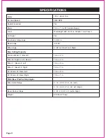
Page 12: ...0 Right Max Cutting Capacity Crosscut Miter 0 Bevel 0 14 in x 4 in Miter 45 Right Left Bevel 0 10 in x 4 in Miter 0 Bevel 45 Left 14 in x 2 in Miter 0 Bevel 45 Right 14 in x 1 in 45 Miter 45 Bevel Lef...

Page 13: ...ardous and could cause serious personal injury A 1 Miter Saw Assembly B 1 Dust Bag C 1 Work Piece Clamp The following items are included with your miter saw CONTENTS A E F B C D PART DESCRIPTION QUANT...

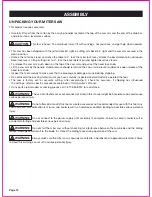
Page 14: ...13 ASSEMBLY This product requires assembly Carefully lift saw from the carton by the carrying handles located at the top of the saw arm and the end of the slide bar and place it on a level work surfac...

Page 15: ...use the head lock knob to hold the cutting head in a down position for cutting operations NOTICE To avoid damage never carry the miter saw by the blade guard power cord miter lock lever or cutting he...

Page 16: ...lywood K Fig 3c Bolt the base of the miter saw securely to the plywood using the mounting holes A Fig 3a on the base Use C clamps not included to clamp this mounting board to a stable work surface at...

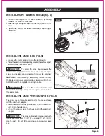
Page 17: ...ise Slide the right sliding fence B into the slot C on the miter fence Tighten the sliding miter fence lock knob A by turning it clockwise FIG 4 A NOTICE To avoid damage never carry the miter saw by t...

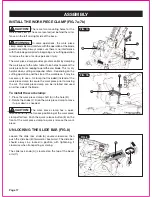
Page 18: ...7a FIG 7b INSTALL THE WORK PIECE CLAMP FIG 7a 7b The work piece clamp provides greater control by clamping the work piece to the miter table It also helps to prevent the work piece from creeping towar...

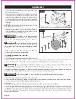
Page 19: ...otion the blade in table slot If either side of the table insert hits the saw blade loosen the four screws for that side and adjust Tighten the screws and check again for blade clearance NOTICE Do not...

Page 20: ...r flange F with double D flats on the outer flange align with the flats on the arbor Replace flat washer E and thread the arbor bolt C onto the arbor in a counter clockwise direction Fig 10c Place the...

Page 21: ...blade wrench D is located in the left side of the rear carrying handle FIG 11 WARNING To avoid injury never use the saw without the cover plate securely in place It keeps the arbor bolt from falling...

Page 22: ...uare C on the miter table with one leg of the square against the table and slide the other leg of the square against the flat part of the saw blade If the blade is not 0 to the miter table loosen two...

Page 23: ...sing a combination square check to see if the blade is 48 to the table To adjust turn the screw J located on the left of the cutting arm clockwise or counter clockwise with 10mm wrench adjustment wren...

Page 24: ...using the hex key on the blade wrench Lay a framing square B flat on the miter table Place one leg of the square against the miter fence C Slide the other leg of the square against the flat part of s...

Page 25: ...l the adjustment steps are complete and you have read and understood the safety and operational instructions THE LASER GUIDE FIG 16a 16d Your tool is equipped with a laser guide using a class II laser...

Page 26: ...ght until the laser line is properly aligned Fig 16c ADJUSTMENT WARNING Use of controls or adjustments or performance of procedures other than those specified herein may result in hazardous radiation...

Page 27: ...g your hands and raising the cutting head Unplug the miter saw Before freeing jammed material Release trigger switch Wait for all moving parts to stop Unplug the miter saw FIG 17 WARNING To reduce the...

Page 28: ...N OFF switch C to OFF position LED WORKLIGHT ON OFF SWITCH FIG 18 This miter saw is equipped with a LED worklight to illuminate work surface under low light conditions To turn LED worklight ON press L...

Page 29: ...e front of the work piece clamp B Move the work piece clamp B upward or downward to the desired position Release the quick release button A to secure the clamp the work piece Turn the knob C for sligh...

Page 30: ...o the off position automatically CHOP CUTS FIG 23 Chop cuts are used mainly for narrow pieces A Unplug the saw Turn the slide lock knob B counter clockwise to release the slide bar C Slide the cutting...

Page 31: ...osition the work piece Make sure the work piece is clamped firmly against the table and the fence Loosen the slide lock knob Plug the saw into an electrical outlet Grasp the D handle and pull the cutt...

Page 32: ...ht or 60 right by noting the stops or clicks at these angle settings Pull down the miter lock lever to lock the miter table Plug the saw into an electrical outlet Pull out the head lock knob to releas...

Page 33: ...d 48 right or left Unplug the saw Mark the cutting line on the work piece with a pencil Make sure that the miter table is positioned at 0 and locked with the miter lock lever Pull out the head lock kn...

Page 34: ...N OFF switch trigger Allow several seconds for the blade to reach maximum speed Slowly lower the blade into and through the work piece Complete the cut Release the ON OFF switch trigger Allow the saw...

Page 35: ...sition before making a cut Plug the saw into an electrical outlet Place the work piece flat on the miter table with one edge securely against the fence If the board is warped place the convex side aga...

Page 36: ...ece away from the fence with a scrap piece of lumber approxiamtely 1 1 2 in thick This will allow for a complete groove to be cut Be sure the work piece is fully supported Plug the saw into an electri...

Page 37: ...on B The cut stop C is designed for using during repetitive cutting Only use one cut stop at a time Rotate the cut stop C to vertical position FIG 30b FIG 31 WORKPIECE SUPPORT AND REPETITIVE CUTTING U...

Page 38: ...LDING FLAT ON THE MITER TABLE FIG 33 To use this method for accurately cutting crown moulding for a 90 inside or outside corner lay the moulding with its broad back surface flat on the miter table and...

Page 39: ...ide is finished piece Outside Corner Left side Position top of moulding against fence LEFT side is finished piece Outside Corner Right side Position top of moulding against fence RIGHT side is finishe...

Page 40: ...nt amount of high grade lubricant for the life of the unit under normal operating conditions Therefore no further lubrications are required WARNING Failure to unplug the saw could result in accidental...

Page 41: ...ing parts Parts failure Pivot spring not replaced properly after service Sawdust buildup Cutting head cannot fully raise or blade guard cannot fully close Use miter lock lever See ADJUSMENT section Va...

Page 42: ...er D Saw Blade E Outer Flange F Inner Flange G H Arbor Bolt I Blade Wrench J Table Insert Lower Blade Guard PART DESCRIPTION PART K L Dust Bag M Sliding Miter Fence Lock Knob N Table Extension Lock Kn...

Page 43: ...that has resulted from abuse or misuse of the Merchandise This warranty 1 excludes expendable parts including but not limited to blades brushes belts bits light bulbs and or batteries 2 shall be void...

Page 44: ......

Reviews: