46
DO NOT DIVE.
1
DO NOT DIVE.
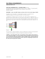
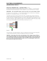
AS MANUFACTURED – SINGLE SERVICE
(Figure 1)
Single Service, TN and TT Electrical Systems (1x16 Amp or 1x32 Amp)* 3 Wires (1 Line + 1 Neutral
+ 1 Protective Earth). Protective Earth wire (Green/Yellow) must be connected to system ground
terminal as marked. All equipment (pumps, heater, etc.) runs on service line L1. Heat Disable dip
switches must be evaluated to prevent the swim spa maximum ampacity from exceeding the
service maximum ampacity. Dip switch settings should not be changed from factory settings in this
configuration.
NOTE: This option is configured and shipped as the default.
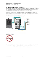
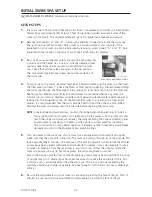
OPTIONAL CONFIGURATION – 2 SERVICE/PHASE
(Figure 2)
Dual Service, TN and TT Electrical Systems (2x16 Amp). 5 Wires (2 Lines + 2 Ne 1 Protective
Earth)*. Protective Earth wire (Green/Yellow) must be connected to system ground terminal as
marked. The heater runs on service line L1. All equipment (pumps, etc.) runs on service line L2.
IMPORTANT
–
Each service MUST include a neutral wire, with a line to neutral voltage of 230VAC.
From the original factory configuration, remove the black wires from Section 1, J51 & J52 to
Section 3, J88 & J62. Move the white wires in Section 2, at J72, J47, & J61 and reconnect them in
Section 4, at J75, J77, & J54. Heat Disable dip switches must be evaluated to prevent the swim spa
maximum ampacity from exceeding the service maximum ampacity (L1, L2).
Ground
ELECTRICAL REQUIREMENTS
MS6013XE HOOK-UP
Figure 1
Brown L1
Blue N
Ground
1
2
3
4
Figure 2
Brown L2
Blue N
Brown L1
Blue N
1
2
3
4
* Must be sized to swim spa
specification. Swim spa rated
maximum ampacity cannot
exceed the service maximum
ampacity. This does not
represent an option to the
Installer.

