background image

18

106813

PORTABLE GASOLINE GENERATORS

R

250V 30A 

Receptacle

250V 50A

  Receptacle     

125V, 15A

Receptacle

GFCI 125V, 15A

Receptacle

125V, 30A

Receptacle

Circuit

Breaker

20A

Circuit

Breaker

20A

Green

Green

Black

Black
White

Black

Red

Black

Black

Black

Black

Black

White

White

White

Green

Black

Black

Black

Red

Red

Red

Red

Yellow

Yellow

White
White

Auto-Idle

Control Board

Yellow

White

White

White

Circuit

Breaker

30A

Circuit

Breaker

30A

Circuit

Breaker

45A

Circuit

Breaker

45A

Green

T2

Green

Black

Red

White

Main

Windings

T1

T3

T4

Wh

T1

T2

T3

T4

Rotor

Diode

Diode

Stator

Capacitor

White

White

Run

Light

Hour Meter

Gree

n

L1

S2

Solenoid

S1

T1-3

L2

To

Auto-Idle

Solenoid

Stator

110/120V

T1

T2

T3

T4

L2

L1

110/120V

220/240V

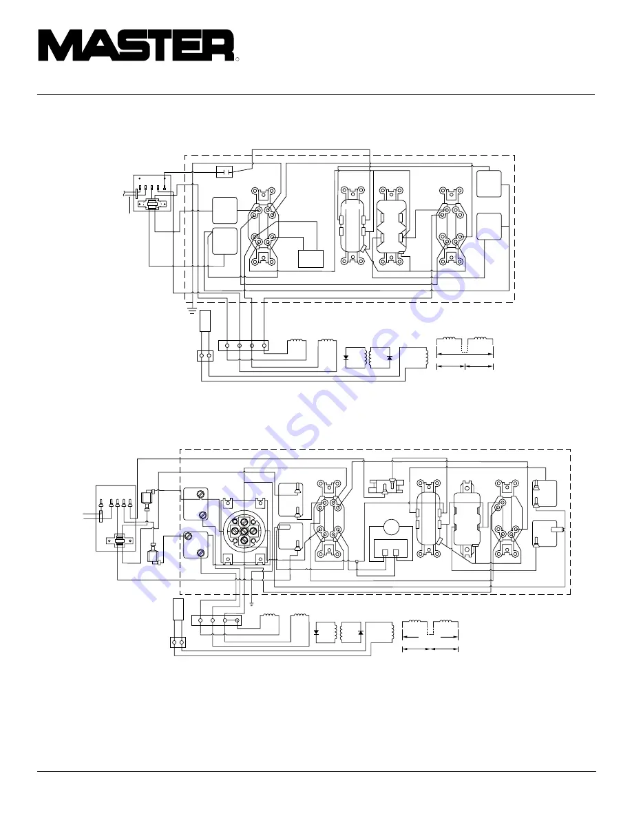
Figure 36 - Wiring Diagram, Model MGH10000A

WIRING DIAGRAMS

Continued

Figure 35 - Wiring Diagram, Model MGH6500IE

120/240V 30A 

Receptacle

T4

120V, 15A

Receptacle

Circuit

Breaker

20A

Green

Black

Black

Black

Red

Black

T3

White

White

Green

Red

T1

T2

White

Circuit

Breaker

30A

Circuit

Breaker

30A

Black

Red

Yellow

Green/Yellow

Stator

110/120V

T1

T2

T3

T4

L2

L1

110/120V

220/240V

T2

Green

Red

Black

Yellow

Main

Windings

T1

T3

T4

T1

T2

T3

T4

Rotor

Diode

Diode

Stator

White

Brown

Capacitor

White

White

White

GFCI

120V, 15A

Receptacle

Auxiliary

Phase

LINE

WHITE

HOT

120V, 15A

Receptacle

Circuit

Breaker

20A

Duplex

To Solenoid

Switch

s

1    

s

2    

Hour

Meter

White

Black

Summary of Contents for HWI3000

Page 1: ...nderstand this manual before operating or servicing generator Improper use of generator can cause serious injury Keep this manual for future reference Generator Models HWI3000 MGH3000G MGH3000 MGH3000PR MGH4000C MGH4000CI MGH5000D MGH5000DI MGH5000DIE MGH6000D MGH6000DI MGH6500IE and MGH10000A ...

Page 2: ...ake certain you read and understand all warnings Keep this manual for reference It is your guide to safe and proper operation of this generator Safetyinformationappearsthroughoutthese instructions Pay close attention to them Below are definitions for the safety infor mation listed throughout this manual DANGER indicates a hazard which will causeseverepersonalinjury death orsubstan tial property da...

Page 3: ...moke or flames if it vibrates at high levels if it has a damaged receptacle 12 Keep generator and nearby areas clean Keep generator free of oil mud and other foreign matter Remove anything that creates slip pery areas around generator Remove oily rags and other items that create fire hazards Keep a fire extinguisher nearby Make sure it is rated ABC by the NFPA They are good for all uses Consult yo...

Page 4: ... parts Check for shipping damage If any parts are missing or damaged promptly inform dealer where you bought generator 4 Battery cables are supplied for models MGH5000DIE MGH6500IE and MGH10000A only These cables are in a separate bag inside generator carton You must install these cables to engine See Battery page 8 for installation in structions Thisgeneratorneedscoolingairtorunprop erly Never bl...

Page 5: ...l Oil Alert System Yes Yes Yes Yes Yes Yes Start Method Recoil Recoil Recoil Recoil Recoil Recoil Elec Weight pounds 85 5 85 5 85 5 84 139 173 Single phase 1 0 power factor Single phase 1 0 power factor MGH6000D MODEL MGH6000DI MGH6500IE MGH10000A Electrical Rated Wattage 6000 6500 10 000 Rated Amperage 120 V 50 57 83 3 240 V 25 28 3 41 7 Receptacle 120 V Duplex Yes Yes Yes 120 V 20 A Duplex 120 V...

Page 6: ...models except HWI3000 MGH3000G MGH3000 MGH3000PR MGH6500IE andMGH10000Ahaveafullpowerselector switch on the control panel The switch has two positions 120 VOLT ONLY and 120 240 VOLT 120 VOLT ONLY This position sends full power to the 120V receptacles only 240V power is not available Use this position when powering 120V items only 120 240VOLT Thispositionsendsfullpower to the 120 240V receptacle It...

Page 7: ...H10000A only the oil should be between the two dots on dipstick 3 If level is low fill to top of oil filler neck see Figure 7 For Model MGH10000A only fill to top dot on dipstick Only use oil recommended in engine owner s manual Note If oil level is too low oil alert system will shutdown engine and prevent engine from restarting Note High ambient temperature will cause nuisance tripping Figure 7 C...

Page 8: ...onotovertighten positive terminal on starter sole noid Positive terminal could ro tate and cut into negative termi nal causing a short IMPORTANT Make sure battery connec tions are the correct polarity Electric start generators use negative ground 12 volt DC starting system Models MGH5000DIE MGH6500IE and MGH10000A have an electric starter A battery is not supplied with generator You must provide a...

Page 9: ...evels are full Make sure battery is charged See engine owner s manual for more information Battery Hook Bolt Nut GENERATOR GROUNDING Ground Lug Ground Wire Alternator Copper or Brass Grounding Point Figure 16 Grounding Generator Model MGH4000C Shown EXTENSION CORDS Only use grounded extension cords Be sure touseextensioncordwithproperwiregauge size See chart below Recommended Minimum Wire Gauges A...

Page 10: ... Step 3 carefully 1 Make two lists of items you want pow ered by generator List all motors and motor powered appliances in one List all lights small appliances etc in the other For standby service to home or building only include items you must power 2 Enter running watts of each item ex cept motors The light bulb or appliance nameplate lists its wattage Remember 1KW 1000 watts Note The name plate...

Page 11: ...g rating will trip re ceptacle circuit breaker Use receptacles properly Improper use could damage generator Use only grounded exten sion cords Power only grounded or double insulated items Do not overload receptacles All generators except models HWI3000 MGH3000G MGH3000 and MGH3000PR havethefollowingreceptacles seeFigure17 120V 15 amp GFCI duplex receptacle 120V 30 amp twist lock receptacle 120 24...

Page 12: ... Figure 20 or choke button out for Model MGH10000A see Figure 21 This closes the choke Note You may not need to close choke if engine is warm or air temperature is high WARNING Only responsible adults should use generator Neverletanyoneoperategenera tor without proper instructions PRESTART Operate generator on a firm dry and clean surface The surface must be level Protect generator from heavy dust...

Page 13: ...s up again and again 1 Turn Auto Idle switch OFF Start en gine Allow engine to warm up with no load for five minutes Solenoid Mounting Bracket Bolt OF F EN GI NE Solenoid Mounting Bracket M8 Nut Figure 27 Solenoid Bracket Location Models MGH4000CI MGH5000DI MGH5000DIE MGH6000DI and MGH6500IE Only Figure 28 Solenoid Bracket Location Model MGH10000A Only Figure 26 Control Panel Auto Idle Switch 2 Re...

Page 14: ...Rs and other home electronic items STOPPING ENGINE IMPORTANT The engine speed is preset The throttle is locked in preset position Do not adjust throttle Follow the steps below to stop engine 1 Remove all electrical loads from gen erator see Disconnecting Electrical Loads Remove electrical loads one at a time 2 Let engine run for two or three min utes after removing electrical loads This lets engin...

Page 15: ...te See engine owner s manual for engine troubleshooting SERVICING THE ENGINE Honda parts and services should be handled by your nearest authorized engine service firm Check the yellow pages of your tele phone directory under the listing Engines Gasoline Honda or visit www honda engines com or call Honda direct 1 800 426 7701 IMPORTANT Keep generator level while in storage Never store generator ups...

Page 16: ...00DI 0 54 1 38 0 61 2 29 50 70 Amp MGH5000DIE 0 54 1 38 0 61 2 29 50 70 Amp MGH6000D MGH6000DI 0 37 1 01 0 68 2 57 60 70 Amp MGH6500IE 0 28 0 78 0 77 2 9 70 70 Amp MGH10000A 0 40 0 90 0 37 0 50 80 70 Amp ELECTRICAL COMPONENT SPECIFICATIONS Connect T2 green and T3 black Measure resistance between T1 red and T4 yellow Resistance between brown and white leads Remove diodes to check resistance T2 Stat...

Page 17: ...hite Figure 32 Wiring Diagram Models MGH4000C MGH5000D and MGH6000D Continued WIRING DIAGRAMS Continued Figure 34 Wiring Diagram Models MGH4000CI MGH5000DI MGH5000DIE and MGH6000DI Circuit Breaker 20A 25A or 30A 120 240V 20A Receptacle T4 120V 15A Receptacle 120V 30A Receptacle White White Green Black Red Black Red Black White T3 Red Green Stator 110 120V T1 T2 T3 T4 L2 L1 110 120V 220 240V Rotor ...

Page 18: ...e White Run Light Hour Meter Green L1 S2 Solenoid S1 T1 3 L2 To Auto Idle Solenoid Stator 110 120V T1 T2 T3 T4 L2 L1 110 120V 220 240V Figure 36 Wiring Diagram Model MGH10000A WIRING DIAGRAMS Continued Figure 35 Wiring Diagram Model MGH6500IE 120 240V 30A Receptacle T4 120V 15A Receptacle Circuit Breaker 20A Green Black Black Black Red Black T3 White White Green Red T1 T2 White Circuit Breaker 30A...

Page 19: ...dering parts fol low the instructions listed under Replace ment Parts on page 32 of this manual Includes fastening hardware Includes reference numbers 1 through 22 Parts not available Included in alternator assembly KEY PART NO NUMBER DESCRIPTION QTY 099722 01 Alternator Assembly HWI3000 1 099722 02 Alternator Assembly MGH3000G MGH3000 and MGH3000PR 1 1a 099849 01 Top Cover HWI3000 1 1b 100074 01 ...

Page 20: ...tator 1 14 27003002 27003002 27003002 27003002 Fan Bracket 1 15 27003015S 27003015S 27003015S 27003015S Screw M8 x 20 4 16 099891 01 099891 01 099891 01 099891 01 Rotor Nut Flanged 8mm 1 17 099892 01 099892 01 099892 01 099892 01 Foam Pad 1 18 099842 01 099842 02 099842 03 099842 04 Draw Bolt 1 19 27003003 27003003 27003003 27003003 Bearing 1 20 27003012S 27003012S 27003012S 27003012S Diode 2 21 R...

Page 21: ...R QTY 1 Stator 1 2 Rotor 1 3 Draw Bolt 103188 01 1 4 Fan 103191 01 1 5 Balancing Disc 103192 01 1 6 Lifting Eyes 103193 01 2 7 D E Bracket 103194 01 1 8 N D E Bracket 103195 01 1 9 Mounting Bolts 099847 05 4 10 Nuts 099891 01 4 11 Top Box 103189 01 1 12 Screw and Washer 099701 01 6 13 Plastic Cap 103198 01 1 14 Bearing 103199 01 1 15 Borelly Washer 103200 01 1 16 Diode 27003012S 2 17 Terminal Bloc...

Page 22: ... 2 8 19165004 5 16 18 x 1 Screw 1 9 04110002 5 16 18 x 11 2 Screw 1 10 099767 01 Isolator Spacer 1 11 21834000 5 16 x 11 2 Washer 1 12 19166004 5 16 18 x 2 Screw 2 Note Fuel tank is available from Engine Mfg Co only ILLUSTRATED PARTS LIST For Model MGH3000G Alternator Assembly This list contains replaceable parts used in yourgenerator Whenorderingparts follow the instructions listed under Replacem...

Page 23: ...sted under Replacement Parts on page 32 of this manual 1 2 3 4 5 3 4 3 4 5 3 4 3 6 6 7 9 3 3 3 7 4 4 3 4 5 8 KEY PART NO NUMBER DESCRIPTION QTY 1 105155 01 Roll Cage 1 2 099754 01 Engine Spreader 1 3 NEC 5C Lock Nut 5 16 18 9 4 WP 5C Flat Washer 5 16 7 5 099853 02 Shock Mount 3 6 04110002 Screw 5 16 18 x 11 2 2 7 14138000 Ground Strap 1 8 21834000 Washer 5 16 x 11 2 1 9 100406 01 Bolt 5 16 18 x 3 ...

Page 24: ...11 16 21 20 19 14 23 14 23 23 16 16 16 10 11 16 11 16 22 F U E L F 1 3 2 4 24 7 8 6 6 27 7 25 15 5 26 F U E L F 10 10 29 24 1 2 24 29 24 28 9 24 28 ILLUSTRATED PARTS LIST For Models MGH4000C MGH4000CI MGH5000D MGH5000DI MGH5000DIE MGH6000D MGH6000DI and MGH6500IE Fuel Tank and Roll Cage ...

Page 25: ...56 01 099756 01 099756 01 Engine Spreader 1 19 099750 01 099750 01 Hook Bolt 5 16 18 2 20 099749 01 099749 01 Battery Mounting Bracket 1 21 NEC 5C NEC 5C Lock Nut 5 16 18 2 22 100410 01 100410 01 100410 01 100410 01 Sems Screw 8 18 x 1 2 4 23 M10908 74 M10908 74 M10908 74 Screw 1 4 20 x 1 2 3 M10908 74 M10908 74 Screw 1 4 20 x 1 2 2 24 WP 4C WP 4C WP 4C WP 4C Washer 1 4 4 25 099965 01 099965 01 09...

Page 26: ... 37 29 36 26 10 37 28 12 10 16 27 2 37 10 10 25 10 9 35 1 7 3 6 5 6 9 10 4 9 10 36 9 24 22 8 12 11 25 37 10 10 21 21 20 20 19 19 18 32 9 31 34 30 33 18 F U E L F 17 10 9 15 14 13 ILLUSTRATED PARTS LIST For Model MGH10000A Fuel Tank and Roll Cage ...

Page 27: ...106988 01 Barbed Connector 1 4 1 17 25985008 Fuel Line 1 18 105035 01 Handle 2 19 103046 01 Grip 2 20 103057 01 Plug 2 21 H8C5 20C Bolt 5 16 18 x 2 5 4 22 099750 01 Bolt J Hook 5 16 18 2 23 099749 01 Battery Bracket 1 24 105908 01 Battery Mount 1 25 17529000 Shock Mount 3 26 102962 02 Spreader 1 27 H5C4 24C Bolt 1 4 20 x 3 4 28 26302006 Bolt 1 2 10 x 1 2 29 WLI 8 Internal Tooth Lockwasher 2 30 141...

Page 28: ...350 01 Hour Meter 1 10 099760 01 099760 01 099760 01 099760 01 Bushing 1 11 100410 01 100410 01 100410 01 100410 01 Sems Screw 8 18 x 1 2 4 12 100149 01 100149 01 100149 01 100149 01 Control Box 1 13 22261000 22261000 22261000 22261000 U Nut 8 14 099997 01 099997 01 099997 01 099997 01 Switch Plug 1 103348 01 103348 02 103348 03 Control Panel Assembly 1 103348 05 103348 06 103348 07 103348 09 Cont...

Page 29: ... 22616010 Circuit Breaker 30 Amp 2 13 099760 01 Bushing 1 14 103185 01 Control Box 1 15 100366 01 Rocker Switch 1 16 104202 01 120V 20A Duplex Receptacle 1 102927 01 Control Panel Assembly 1 100177 05 Panel Schematic Diagram 1 103257 01 Auto Idle PC Board Kit 1 103258 02 Solenoid Assembly Kit With Bracket 1 Rese t Rese t Rese t Rese t Rese t Rese t 120 Volt Auto Idle 200 Vp t Selector 1 4 14 Off O...

Page 30: ... GENERATORS R DESA IN TERNATIO NAL S2 S1 L1 L2 1 2 4 5 3 8 7 14 13 10 12 11 9 8 10 6 Control Board Assembly and Mounting Solenoid Assembly and Mounting ILLUSTRATED PARTS LIST For Solenoid and Control Board Assemblies and Mounting ...

Page 31: ... 100321 01 Nylon Spacer 4 4 WP C3 Flat Washer 10 4 5 26514000 Lock Nut 10 32 4 6 100324 03 Solenoid Assembly Includes Plunger Nut and Lock Washer 1 7 103812 01 Retaining Ring 1 8 100755 02 Linkage Rod 1 100755 01 Linkage Rod 1 9 22822000 Roll Pin 1 10 102939 01 Solenoid Mounting Bracket 1 100756 01 Solenoid Mounting Bracket 1 11 103811 01 Nylon Washer 1 12 100328 01 Bolt M8 x 25mm 1 13 02407002 Fl...

Page 32: ... not supply the part or acces sory contactyournearestPartsCentrallisted below EachAuthorizedDealer Authorized Service Center and Parts Central is inde pendently owned and operated See pages 19 through 31 for an Illustrated Parts List If you need additional referral information contact our Technical Service Department see Technical Service page 15 In Canada call 1 800 561 3372 for parts information...

Page 33: ...____________________ _______________________________________________________________________________________________ _______________________________________________________________________________________________ _______________________________________________________________________________________________ ___________________________________________________________________________________________...

Page 34: ...____________________________ _______________________________________________________________________________________________ _______________________________________________________________________________________________ _______________________________________________________________________________________________ ___________________________________________________________________________________...

Page 35: ...____________________ _______________________________________________________________________________________________ _______________________________________________________________________________________________ _______________________________________________________________________________________________ ___________________________________________________________________________________________...

Page 36: ...on modification tampering contaminated fuels repair using improper parts or repair by anyone other than an authorized dealer or service center Routine maintenance is the responsibility of the owner Travel handling transportation and incidental costs associated with warranty repairs are not reimbursable under this warranty and are the responsibility of the owner To the full extent allowed by the la...

Reviews: