background image

8

114716

PORTABLE GASOLINE GENERATORS

R

120

/240

V

TW

IST

LOC

K

120

V

TW

IST

LOC

K

120

V

GFC

I

120

V

VOL

TAG

E

HO

UR 

ME

TER

AUT

O-ID

LE

RES

ET

RES

ET

RES

ET

RES

ET

OFF

ON

SEL

ECT

OR

120

ON

LY

120

+

240

RE

SE

T

TE

ST

EN

M

00

00

00

05

HO

UR


  1

/1

0

E

F

FUEL

STANDBY 

INSTALLATION 

TO HOME OR 

BUILDING

  WARNING:  The  electrician 

must  install  a  double-throw 

transfer switch. This isolates ex-

isting electrical circuits from the 

utility power line. If not isolated, 

generator output will back-feed 

into utility power line. This may 

electrocute a power company line 

repair person.

IMPORTANT:

  This  generator  will  not 

power your entire home. Most home utility 

electric service is more than 60 amps. This 

will exceed generator output. Only power 

needed items during a power outage. Make 

sure total wattage of electrical load does not 

exceed rated wattage of generator.
You  may  need  to  use  this  generator  as  a 

standby power source. During a power out-

age, the generator will power selected items 

in a building. Have generator and additional 

wiring  installed by a skilled, licensed electri-

cian. This is not a do-it-yourself job. Follow 

all local codes.

 WARNING: Have standby in-

stallation performed by a skilled, 

licensed  electrician.  Do  not  let 

anyone  else  wire  into  a  utility 

circuit.  Personal  injury,  equip-

ment damage, or damage to home 

could occur.

 Ampere 

AWG for Length of  

  Load 

Cord in Feet


50' 

100' 

150'


18 

18 

18


18 

18 

18


16 

16 

16


16 

16 

16


16 

16 

14


16 

14 

12


10 

16 

14 

12


12 

14 

14 

12


14 

14 

12 

10


16 

12 

12 

10


20 

10 

10 

8

GENERATOR 

GROUNDING

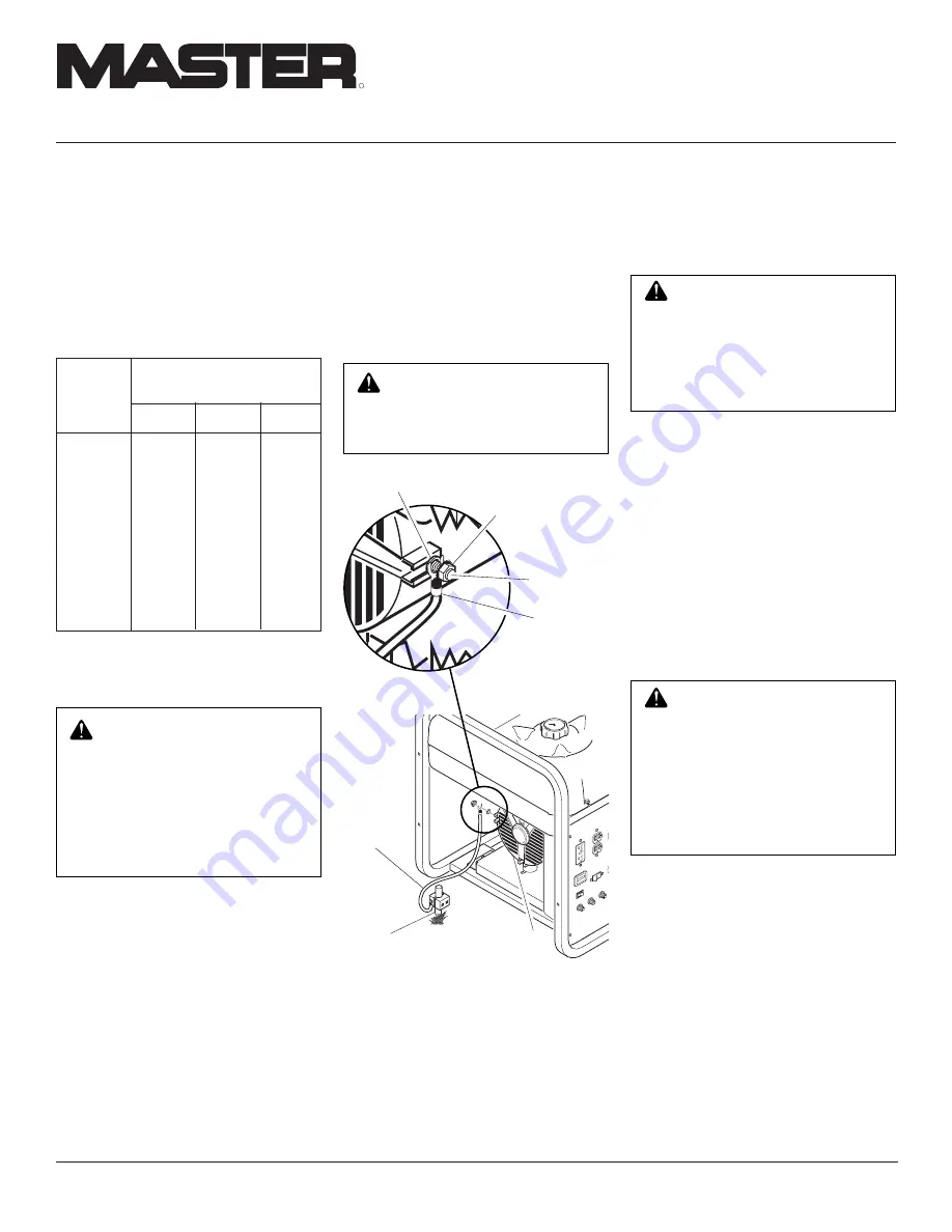
Ground 

Wire

Alternator

Copper or Brass 

Grounding Point

Figure 7 - Grounding Generator (Model 

MGR4500I Shown)

EXTENSION 

CORDS

Only use grounded extension cords. Be sure 

to use extension cord with proper wire gauge 

size. See chart below.

Recommended Minimum Wire 

Gauges (AWG) for Extension 

Cords

 WARNING: For a grounding 

point, do not use metal pipe be-

ing  used  to  carry  combustible 

materials or gases.

Grounding generator helps prevent electric 

shock from a ground fault condition. Follow 

these steps to ground your generator:
1.  Locate ground bolt on generator hous-

ing (see Figure 7).

2.  Loosen SEM nut on ground bolt. 

Note:


Do not remove SEM nut from bolt.

3.  Attach a spade connector to the end of 

a #10-8 stranded-copper ground wire.

4.  Attach spade connector to ground bolt 

between flat washer and SEM nut (see 

Detail A in Figure 7).

  WARNING:  You  must  prop-

erly  earth-ground  generator  be-

fore starting. This will help guard 

against deadly electric shock. Only 

use grounded plugs with genera-

tor. Only use grounded extension 

cords.  Only  use  three-wire  or 

double-insulated power tools.

120

/240

V

TW

IST

LOC

K

120

V

TW

IST

LOC

K

120

V

VOL

TAG

E

HO

UR 

ME

TER

AUT

O-ID

LE

RES

ET

RES

ET

RES

ET

RES

ET

OFF

ON

SEL

ECT

OR

120

ON

LY

120

+

240

ENM

000

000

05

HO

UR

S    

  1/1

0

E

F

FUEL

Ground Bolt

Flat Washer

Spade 

Connector

SEMS Nut

Detail A

5.  Drive  grounding  point  into  ground. 

Note:

 Grounding point can be a stake, 

grounding  rod,  or  pipe.  Grounding 

point should be copper or brass.

6.  Attach ground wire to grounding point.
You must supply the ground wire and ground-

ing point. These do not come with generator. 

Follow the National Electrical Code and all 

state and local codes. Consult your power 

company or a licensed electrician.

Summary of Contents for MGR2900, MGR4500I, MGR6000I

Page 1: ...N AND INSTALLATION MANUAL R IMPORTANT Read and understand this manual before operating or servic ing generator Improper use of generator can cause serious injury Keep this manual for future reference Generator Models MGR2900 MGR4500I and MGR6000I ...

Page 2: ... and understand all warnings Keep this manual for reference It is your guide to safe and proper operation of this generator Safetyinformationappearsthroughoutthese instructions Pay close attention to them Belowaredefinitionsforthesafetyinforma tion listed throughout this manual DANGER indicates a hazard which will cause severe personal injury death or substantial property damage if you ignore warni...

Page 3: ...al output drops if it is sparking if it produces smoke or flames if it vibrates at high levels if it has a damaged receptacle 12 Keep generator and nearby areas clean Keep generator free of oil mud and other foreign matter Remove anything that creates slip pery areas around generator Remove oily rags and other items that create fire hazards Keep a fire extinguisher nearby Make sure it is rated ABC b...

Page 4: ...ssing parts Check for shipping damage If any parts are missing or damaged please contact our Technical Service Department at 1 800 858 8501 English Only Thisgeneratorneedscoolingairtorunprop erly Never block free flowing cooling air togenerator Overheatingwilloccurwithout cooling air This will damage the generator Keepgeneratoratleastthreefeetawayfrom any object DANGER Use only in well vented areas...

Page 5: ...ock 20 Amp 30 Amp 120 V Voltage Selector Switch Yes Yes General Robin Engine H P 6 9 11 5 Robin Model EX170 D52010 EX270 0638T EH360 0644T Fuel Type Gasoline Gasoline Gasoline Fuel Tank Capacity 3 9 qt 8 gal 8 gal Oil Alert System Yes Yes Yes Start Method Recoil Recoil Recoil Weight pounds 85 5 135 165 Single phase 1 0 power factor Note Ratings apply to SAE standard conditions Reduce ratings 3 1 2...

Page 6: ...shuts down the engine the engine will not start until you add oil Add oil to engine see Engine Oil page 7 Note Operate generator on a level surface If not level the oil may flow away from the oil level sensing device This will cause the oil alert system to shut down engine See engine owner s manual for more information Figure 2 Engine Switch Location ENGINE SW ON OFF 120 240 VOLT Position 120 VOLT ...

Page 7: ...ould cover most of dipstick 3 If level is low fill to top of oil filler neck see Figure 6 Only use oil recom mended in engine owner s manual Note If oil level is too low oil alert system will shutdown engine and prevent engine from restarting Figure 6 Checking Oil Level Model MGR4500I Shown FUEL Oil Level At Top Of Filler Neck Dipstick Oil GENERATOR FEATURES Continued Use clean fresh unleaded gasoli...

Page 8: ... 12 12 10 20 10 10 8 GENERATOR GROUNDING Ground Wire Alternator Copper or Brass Grounding Point Figure 7 Grounding Generator Model MGR4500I Shown EXTENSION CORDS Only use grounded extensioncords Be sure touseextensioncordwithproperwiregauge size See chart below Recommended Minimum Wire Gauges AWG for Extension Cords WARNING For a grounding point do not use metal pipe be ing used to carry combustib...

Page 9: ...e of generator For rated wattage of your generator see Specifications page 5 Electric motors present a special problem when figuring load Read Step 3 carefully 1 Make two lists of items you want pow ered by generator List all motors and motorpoweredappliancesinone Listall lights small appliances etc in the other For standby service to home or building only include items you must power 2 Enter runnin...

Page 10: ...DANGER Neverconnectgen erator to any existing electrical circuits Thegeneratoroutputwill back feed into the utility power line Thismayelectrocuteapower companylinerepairperson Also ifgeneratorispoweringelectrical circuits the chance of an electri cal fire exists DANGER Use only in well vented areas Make sure area has plenty of free moving fresh outside air Never run generator in an enclosed or confi...

Page 11: ...GR6000I see Figure 11 This closes the choke Note You may not need to close choke if engine is warm or air temperature is high WARNING Only responsible adults should use generator Neverletanyoneoperategenera tor without proper instructions PRESTART Operate generator on a firm dry and clean surface The surface must be level Protect generator from heavy dust sand dirt rain or snow Do not locate genera...

Page 12: ...00I IMPORTANT Adjust the idle speed only If the idle speed becomes too high If the engine idle speed will not regulate enginewants to hunt or speeds up and slows down repeatedly 1 Turn Auto Idle switch OFF Start en gine Allow engine to warm up with no load for five minutes Figure 15 Control Panel Auto Idle Switch 2 Loosen the two m10 bolts mounting the solenoid to the engine see Figures 16 and 17 3...

Page 13: ...s one at a time Re move voltage sensitive items first Voltage sensitive items include TVs VCRs and other home electronic items STOPPING ENGINE IMPORTANT The engine speed is preset The throttle is locked in preset position Do not adjust throttle Follow the steps below to stop engine 1 Remove all electrical loads from genera tor seeDisconnectingElectricalLoads Remove electrical loads one at a time 2 ...

Page 14: ...l service web site at www desatech com www desatech com Note See engine owner s manual for engine troubleshooting SERVICING THE ENGINE Robin parts and services should be handled by your nearest authorized engine service firm Visit www robinamerica com or call Robin direct 1 800 277 6246 IMPORTANT Keepgeneratorlevelwhilein storage Never store generator upside down or standing on end Note Wesupplythe...

Page 15: ... 0 835 1 852 4 91 40 8 Amp MGR6000I 0 741 1 582 5 55 40 8 Amp ELECTRICAL COMPONENT SPECIFICATIONS Connect T2 green and T3 black Measure resistance between T1 red and T4 yellow Resistance between brown and white leads Remove diodes to check resistance T2 Stator 110 120V T1 T3 T2 T4 L2 L1 Rotor Stator White Brown Auxiliary Phase Green Red Black Yellow Main Windings T1 T3 T4 L1 L2 L2 L1 20A Circuit B...

Page 16: ...Ylw Grn Ylw Green Yellow Green Yellow To Alternator Ground To Solenoid Green Yellow To Roll Cage Yellow White White Blue Red Black Black Black Blk Blk Black Black Black Red Red Red Red Red Green 120 240V 20A 30A Receptacle 120V 30A Receptacle 120V 15A Receptacle 120V 20A Receptacle White White Wht Wht Wht Wht Wht White White White White Auto Idle Stator 110 120V T1 T2 T3 T4 L2 L1 110 120V 220 240V...

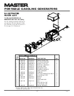
Page 17: ...ted under Replacement Parts on page 23 of this manual Includes fastening hardware Includes reference numbers 1 through 22 Parts not available Included in alternator assembly Available at any hardware store KEY PART NO NUMBER DESCRIPTION QTY 099722 02 Alternator Assembly 1 100074 01 Top Cover 1 2 100445 01 120V 15A Duplex GFCI Receptacle 1 3 22616009 Circuit Breaker 20 Amp 1 4 27002002S Capacitor 1...

Page 18: ...9 115308 01 115308 01 Hex Head Taptite 8mm Screw 4 10 WLE 5 WLE 5 Lock Washer 5 16 4 11 115315 01 115315 01 Bearing 1 12 115316 01 115316 01 Diode 2 13 Rotor Alternator 1 14 115317 01 115317 01 Fan 1 15 Bolt 3 8 16 x 5 8 4 16 Lock Washer 3 8 4 17 115242 01 115242 01 Flange Alternator 1 1 2 3 6 5 4 8 9 10 7 11 12 15 16 17 13 14 ILLUSTRATED PARTS LIST For Models MGR4500I and MGR6000I Alternator Asse...

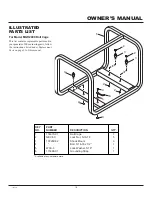
Page 19: ...olt 5 16 18 x 1 2 1 5 WLE 5 Lock Washer 5 16 1 6 115388 01 Grounding Strap 1 ILLUSTRATED PARTS LIST For Model MGR2900 Roll Cage This list contains replaceable parts used in yourgenerator Whenorderingparts follow the instructions listed under Replacement Parts on page 23 of this manual 3 2 2 4 5 3 2 2 3 2 6 3 1 Available at any hardware store ...

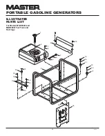
Page 20: ...UTO ID LE RESET RESET RESET RESET OFF ON SELE CTO R 12 0 ONLY 12 0 24 0 RE SE T TE ST EN M 00 00 00 05 HO UR S 1 1 0 E F F U E L Un leaded Gasoline Only SAFETY INFORMATION 14 9 8 16 10 11 13 12 12 13 17 15 16 17 18 15 16 1 2 15 3 10 4 6 5 7 15 ILLUSTRATED PARTS LIST For Models MGR4500I and MGR6000I Fuel Tank and Roll Cage ...

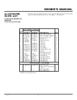
Page 21: ... 11 114685 01 114685 01 Spacer 1 12 Bolt 5 16 18 x 1 2 2 13 WLE 5 WLE 5 Lock Washer 5 16 2 14 103289 01 103289 01 Shock Mount 1 15 NEC 5C NEC 5C Lock Nut 5 16 18 4 16 WP 5C WP 5C Flat Washer 5 16 3 17 103289 02 103289 02 Shock Mounts 2 18 114721 01 114721 02 Control Panel 1 PARTS AVAILABLE NOT SHOWN 100003 06 100003 06 Operation Decal 1 5 16 18 x 1 2 Grounding Bolt 1 5 16 Flat Washer 1 5 16 SEMS N...

Page 22: ... 099760 02 Bushing 1 11 114722 01 114722 01 Enclosure 1 12 116475 01 116475 01 Plastite Pan Head Screw 6 13 100366 01 100366 01 Rocker Switch 1 14 115404 01 115404 01 Auto Idle Control Board Kit 1 114721 01 114721 02 Control Panel Assembly 1 114963 01 114963 01 Panel Schematic Decal 1 ILLUSTRATED PARTS LIST For Models MGR4500I and MGR6000I Control Panel This list contains replaceable parts used in...

Page 23: ...S AND ACCESSORIES For original replacement parts and acces sories contact your nearest Authorized DealerorAuthorizedServiceCenterforthis product If they can not supply the part or accessory contactyournearestPartsCentral listed below Each Authorized Dealer Au thorizedServiceCenter andPartsCentralis independently owned and operated See pages 17 through 22 for an Illustrated Parts List If you need a...

Page 24: ...on modification tampering contaminated fuels repair using improper parts or repair by anyone other than an authorized dealer or service center Routine maintenance is the responsibility of the owner Travel handling transportation and incidental costs associated with warranty repairs are not reimbursable under this warranty and are the responsibility of the owner To the full extent allowed by the law...

Reviews: