background image

headline bars

continuation tabs

notes

warnings

headline bars

continuation tabs

notes

warnings

model no. 054-6988-6  |  contact us 1-800-689-9928

28

This Mastercraft product is guaranteed for a period of 

3 years from the date of original retail 

purchase

 against defects in workmanship and materials, except for the following components:

a)  Component A: Batteries, chargers and carrying case, which are guaranteed for a period of 2 years from 

the date of original retail purchase against defects in workmanship and materials;

b)  Component B: Accessories, which are guaranteed for a period of 1 year from the date of original retail 

purchase against defects in workmanship and materials.

Subject to the conditions and limitations described below, this product, if returned to us with proof 
of purchase within the stated warranty period and if covered under this warranty, will be repaired or 
replaced (with the same model, or one of equal value or specification), at our option. We will bear the 
cost of any repair or replacement and any costs of labour relating thereto.

These warranties are subject to the following conditions and limitations:

a)  a bill of sale verifying the purchase and purchase date must be provided;

b)  this warranty will not apply to any product or part thereof which is worn or broken or which has become 

inoperative due to abuse, misuse, accidental damage, neglect or lack of proper installation, operation or 
maintenance (as outlined in the applicable owner’s manual or operating instructions) or which is being 
used for industrial, professional, commercial or rental purposes;

c)  this warranty will not apply to normal wear and tear or to expendable parts or accessories that may be supplied 

with the product that are expected to become inoperative or unusable after a reasonable period of use;

d)  this warranty will not apply to routine maintenance and consumable items such as, but not limited to, fuel, 

lubricants, vacuum bags, blades, belts, sandpaper, bits, fluids, tune-ups or adjustments;

e)  this warranty will not apply where damage is caused by repairs made or attempted by others (i.e. persons 

not authorized by the manufacturer);

f)  this warranty will not apply to any product that was sold to the original purchaser as a reconditioned or 

refurbished product (unless otherwise specified in writing);

g)  this warranty will not apply to any product or part thereof if any part from another manufacturer is 

installed therein or any repairs or alterations have been made or attempted by unauthorized persons;

W

ARRANTY

Summary of Contents for 054-6988-6

Page 1: ...model no 054 6988 6 PLUNGE ROUTER WITH 5 PIECE ROUTER BIT SET IMPORTANT Read and understand this instruction manual thoroughly before using the product INSTRUCTION MANUAL ...

Page 2: ...headline bars continuation tabs notes warnings ...

Page 3: ...nance 23 Troubleshooting 24 Parts List 25 Warranty 28 TABLE OF CONTENTS NOTE If any parts are missing or damaged or if you have any questions please call our toll free helpline at 1 800 689 9928 SAVE THESE INSTRUCTIONS This manual contains important safety and operating instructions Read all instructions and follow them with use of this product ...

Page 4: ...60 Hz Rated power input 10A Horsepower 1 3 4 HP No load speed 0 28 000 RPM Collet capacity 1 4 6 4 mm Plunge stroke 2 1 8 55 mm Base dimension 6 1 2 16 5 cm Micro fine depth Adjusts to 1 256 0 099 mm Depth stop 4 position turret stop Weight 7 lb 11 oz 3 5 kg Noise level 95 dB A Vibration ahi 1 58 m s2 K 1 5 Sub base opening diameter for cutting bit use 1 1 2 3 8 cm ...

Page 5: ...is tool should only be serviced by a qualified service technician For more information call the toll free helpline at 1 800 689 9928 READ ALL INSTRUCTIONS THOROUGHLY SAVE THESE INSTRUCTIONS GENERAL POWER TOOL SAFETY WARNINGS WARNING Read all safety warnings and instructions Failure to follow the warnings and instructions may result in electric shock fire and or serious injury SAVE ALL WARNINGS AND...

Page 6: ...he influence of drugs alcohol or medication A moment of inattention while operating power tools may result in serious personal injury Use personal protective equipment Always wear eye protection Protective equipment such as dust mask non skid safety shoes hard hat or hearing protection used for appropriate conditions will reduce personal injuries Prevent unintentional starting Ensure that the swit...

Page 7: ...roperly maintained cutting tools with sharp cutting edges are less likely to bind and are easier to control Use the power tool accessories tool bits etc in accordance with these instructions taking into account the working conditions and the work to be performed Use of the power tool for operations different from those intended could result in a hazardous situation SERVICE Have your power tool ser...

Page 8: ...ion cutter rotation of the cutter The cutter must be running at full speed before it is lowered to the workpiece When operating the router always hold the handles firmly with both hands Always ensure that your footing is secure when working Be prepared for the reaction torque of the router particularly if the cutter becomes jammed in the workpiece When a plunge cutting operation is completed relea...

Page 9: ...ce Router Bit Set 1 4 6 mm diameter straight cutting bit 1 4 6 mm radius cove bit 1 4 6 mm radius roundover bit 3 8 10 mm radius bead bit 1 8 3 mm radius roman ogee bit KEY PARTS DIAGRAM 9 12 1 2 5 8 13 6 4 10 3 7 11 14 15 KEY PARTS DIAGRAM WARNING Remove the router from the package and examine it carefully Do not discard the carton or any router material until all parts have been examined ...

Page 10: ...1 800 689 9928 10 No Description No Description 1 Trigger switch 9 Depth of cut scale 2 Lock on button 10 Dust extraction adaptor 3 Speed adjuster 11 Chip shield 4 Plunge lock lever 12 Locking screw 5 Spindle lock 13 Lock bolt 6 Collet nut 14 Base plate 7 Depth stop turret 15 Bushing adaptor 8 Depth stop bar KEY PARTS DIAGRAM ...

Page 11: ...hip shield off of the base WARNING To prevent personal injury always disconnect the plug from the power source before assembly adjustment or changing of bits Failure to comply with these instructions could result in accidental start up and possible injury To reduce the risk of injury do not overload the tool Let it work at its own pace Guide the cord carefully to avoid accidentally cutting it Alwa...

Page 12: ... spindle lock To remove the bit 1 Keep the spindle lock button 5 depressed 2 Loosen the collet nut 6 using the wrench provided and remove the bit 3 Release the spindle lock ADJUSTING THE DEPTH OF CUT fig 3 The depth of cut is the distance between the depth stop bar 8 and the depth stop turret 7 The depth of cut can be set in two different ways as follows ASSEMBLY INSTRUCTIONS fig 2 fig 3 Adjusting...

Page 13: ...ter return to its original position 12 Plug the router into an electrical outlet 13 Turn the router on then lower the unit to make the desired cut ADJUSTING THE DEPTH OF CUT USING A PIECE OF WOOD 1 Unplug the router 2 Lower the router as described above 3 Pull the depth stop bar 8 up 4 Between the depth stop turret 7 and the depth stop bar 8 place a piece of wood with a thickness equal to the desi...

Page 14: ...chamfering or grooving 1 Loosen the lock bolts 2 Feed the bars on the edge guide through the holes in the base plate 3 Adjust the distance between the router bit and the edge guide by moving the guide until it is situated at the proper distance 4 Tighten the lock bolts to hold the straight edge guide in position DUST COLLECTION WITH VACUUM ADAPTOR fig 5 The vacuum port is sized to accept a 1 1 4 3...

Page 15: ...epth as described in ADJUSTING THE DEPTH OF CUT position the router so that the bit is directly above the point you plan to cut 2 Release the plunge lock lever by moving it UP to the unlocked position With the router running apply an even downward pressure on the plunge action until the cutter bit reaches the desired depth then move the plunge lock lever DOWN to the locked position do not force th...

Page 16: ...cuts as you become familiar with all of your router s operational abilities To avoid ruining good material make your test cuts on scrap materials For ease of operation and to maintain proper control your router has two handles one on each side of the router base When operating the router always hold it firmly with both hands fig 11 DEEP CUTS The proper cutting depth for each pass is always determi...

Page 17: ...om the power source place the router upside down on the worktable and inspect the finished cut in the workpiece OPERATING INSTRUCTIONS fig 11 Edge guide Edging with plunge base NOTICE Making test cuts in scrap material that is similar to your workpiece is essential Learning how the router s speed depth of cut and cutter bit will react in the workpiece will help you produce quality cuts WARNING Alw...

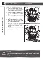
Page 18: ...workpiece 5 When the cutter bit comes to a complete stop unlock the plunge lock lever Up and the plunge action will automatically retract the cutter bit from the workpiece 6 Unplug the router from the power source place the router on the worktable and inspect the finished cut in the workpiece OPERATING INSTRUCTIONS fig 12 Feed direction Edge guide Plunge up set up fig 12a Plunge down cutting WARNI...

Page 19: ...act as a guide fig 13a This guide board must have exactly the same contour straight or curved as the workpiece edge If it is positioned so that its edge is flush with the workpiece edge the bit will make a full cut cutting in as far as the bit radius On the other hand if the guide is positioned so that it extends beyond the edge of the workpiece the bit will make less than a full cut which will al...

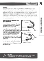
Page 20: ...e cutting bit to be from left to right fig 14 Feeding the bit from left to right will cause the bit to pull the router towards up against the workpiece If the router is fed in the opposite direction right to left the rotating force of the cutting bit will tend to throw the bit away from the workpiece making it hard to control This is called climb cutting cutting in the opposite direction of the pr...

Page 21: ...ard guide must always be positioned on the right hand side of the router as you make the cut fig 15a When the guide is positioned on the right hand side of the router the router travel should be from left to right and counter clockwise around curves fig 15a This counter clockwise action around the curve could cause climb cutting Always be alert and exercise extreme caution to maintain control of t...

Page 22: ...tions the revolutions can become so slow and the bites become so large that chips are only partially cut off causing splintering and gouging of the workpiece The router will make clean smooth cuts if it is allowed to run freely without the overload of forced feeding You can detect forced feeding by the sound of the motor Its usual high pitched whine will sound lower and stronger as it loses speed ...

Page 23: ... not allow brake fluids gasoline and petroleum based products penetrating oil etc come into contact with plastic parts These substances contain chemicals that can damage weaken or destroy plastic When servicing use only identical replacement parts The use of any other parts may create a hazard or cause damage to the product Use only accessories that are recommended for this router by the manufactu...

Page 24: ...cal outlet Connect the plug to a functioning electrical outlet Switch is in OFF position Pull the switch to ON position The surface of the workpiece is not smooth after cutting The bit is dull Change to a sharp bit Routing at an inappropriate bit speed Select an appropriate bit speed If any parts are missing or damaged or if you have any questions please call the toll free helpline at 1 800 689 99...

Page 25: ...25 PARTS LIST EXPLODED VIEW ...

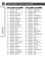
Page 26: ...2 5630036000 Nut 13 3121049000 Spring 43 3660030000 Spring 14 3700249000 Washer 44 3700079000 Spindle lock 15 5700008000 Bearing 45 3123040000 Spindle lock button 16 2740236000 Stator 46 3120300000 Lock cover 17 5610049000 Tapping screw 47 5610083000 Thread forming screw 18 2750831000 Rotor 48 3550572000 Collet 19 5660018000 Circlips for shaft 49 5630034000 Lock nut 20 3122985000 Fan baffle 50 370...

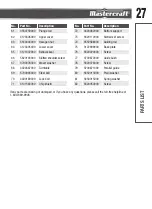
Page 27: ...00 Bellows seal 76 5620220000 Screw 66 5620103000 Slotted shoulder screw 77 3700872000 Guide bush 67 3700078000 Waver washer 78 5620076000 Screw 68 3420387000 Turntable 79 3700871000 Parallel guide 69 5700046000 Steel ball 80 5650013000 Plain washer 70 3400189000 Lock bolt 81 5650015000 Spring washer 71 3121583000 Chip shield 82 5620050000 Screw If any parts are missing or damaged or if you have a...

Page 28: ...g the purchase and purchase date must be provided b this warranty will not apply to any product or part thereof which is worn or broken or which has become inoperative due to abuse misuse accidental damage neglect or lack of proper installation operation or maintenance as outlined in the applicable owner s manual or operating instructions or which is being used for industrial professional commerci...

Page 29: ...t be transferred Neither the retailer nor the manufacturer shall be liable for any other expense loss or damage including without limitation any indirect incidental consequential or exemplary damages arising in connection with the sale use or inability to use this product Notice to Consumer This warranty gives you specific legal rights and you may have other rights which may vary from province to ...

Page 30: ......

Reviews: