headline bars
continuation tabs
notes
warnings
11
headline bars
continuation tabs
notes
warnings
model no. 054-8106-4 | contact us 1-800-689-9928
10
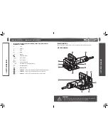
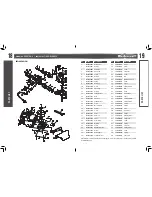
No.
Description
No.
Description
1
Live-tool indicator light
8
Auxiliary handle locking bolt
2
Auxiliary handle
9
Spindle-lock button
3
Angle-guide plate
10
Height-adjustment locking knob
4
Angle-adjustment locking knob
11
Height indicator
5
Centre mark
12
Cutting-depth stopper
6
Angle scale
13
Dust-exhaust port
7
Blade cover
14
On/off switch
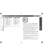
ASSEMBLY INSTRUCTIONS
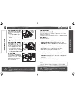
THE LIVE-TOOL INDICATOR LIGHT
The biscuit joiner is equipped with a live-tool indicator light. When the tool is plugged into an electrical
supply, the live-tool indicator light will illuminate to remind you that the tool is plugged in. When the tool
is unplugged, the indicator light will turn off.
ADJUSTING THE DEPTH OF CUT
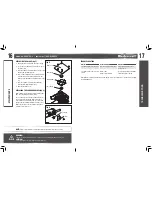
(fig 1)
Four different cutting depths can be preset.
Refer to the table below for the correspondence
between the sizes marked on the cutting depth
stopper and the biscuit size.
Fine adjustments to the cutting depth can be made
by turning the adjusting screw after loosening the hex
nut. This may become necessary after the blade has
been re-sharpened a few times.
Set the cutting-depth stopper to match the size below:
Size on cutting-depth stopper
0
10
20
M
Biscuit size
0
10
20
/
Depth of groove
8 mm
10 mm
12.3 mm
18 mm
ASSEMBL
Y INSTRUCTIONS
WARNING!
• Never connect the biscuit joiner to a power source when you are assembling parts,
making adjustments, installing or removing blade, cleaning, or when it is not in use.
Disconnecting the biscuit joiner will prevent accidental starting, which could cause
serious personal injury.
WARNING!
• Do not allow familiarity with the biscuit joiner to cause a lack of alertness. A fraction of a second of
carelessness is enough to cause severe injury.
FPO
FPO
KEY P
AR
TS DIAGRAM
fig 1
Cutting depth
adjusting screw
Hex nut
Cutting depth
stopper

