headline bars
continuation tabs
notes
warnings
13
headline bars
continuation tabs
notes
warnings
model no. 054-8106-4 | contact us 1-800-689-9928
12
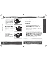
ADJUSTING THE HEIGHT OF CUT
(fig 2)
The angle guide height can be moved up and down to
adjust the position of the blade in relation to the top
of the workpiece.
1. Loosen the height-adjustment locking knob.
2. Move the angle guide up and down until the
indicator points to the desired height on the
height scale.
3. Securely tighten the height-adjustment locking
knob.The height scale indicates the distance from the top of the workpiece to the centre of the
blade.
ADJUSTING THE CUTTING ANGLE
(fig 3)
Most biscuit joining applications require the blade
to cut into the workpiece at a 90° angle. In special
cases, such as mitre joints, it is necessary to insert
the biscuit at a different angle. Adjust the cutting
angles as follows:
1. Loosen the angle-adjustment locking knob, and
tilt the angle guide plate until the indicator points
to the desired angle on the angle scale.
2. Securely tighten the angle-adjustment locking knob.
DUST COLLECTION
(fig 4)
Attach the dust bag to the dust-exhaust port. When
the dust bag is about half full, turn off the tool and
unplug it. Remove the dust bag from the tool. Unzip
the dust bag and empty it.
Alternatively you can attach a suitable vacuum
cleaner to the dust bag adapter.
OPERATION INSTRUCTIONS
TURNING THE BISCUIT JOINER ON/OFF
To turn on the biscuit joiner, slide the switch toward the “l” (ON) position. For continuous operation,
press the front of the switch to lock it.
To turn it off, press the rear of the switch; the switch will return to the “O” (OFF) position automatically.
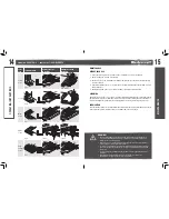
HOW TO MAKE JOINTS
To make joints, proceed as follows:
1. Fit the two workpieces together as they will appear in the finished joint position (refer to fig a-e).
2. Use a pencil to mark the centre of the intended biscuit grooves on the workpiece.
3.
For Corner Joint and T Joint:
Clamp the vertical workpiece to the workbench (fig a1).
For Mitre Joint:
Clamp one workpiece to the workbench with the mitred edge facing up (fig c1).
For Frame Joint and Edge-To-Edge Joint:
Clamp one workpiece to the workbench (fig d1).
4. Set the depth of cut according to the size of the biscuit to be used. Refer to the table in the
“Adjusting the depth of cut”
section.
5. Adjust the angle guide height so that the blade is centred in the board thickness.
6. Align the centre mark on the base with the pencil line on the workpiece.
7. Turn on the tool and gently push it forward in order to extend the blade into the workpiece.
8. Gently pull the tool back to its original position after the cutting depth adjusting screw reaches the
cutting-depth stopper.
9.
For Corner Joint and T Joint:
Clamp the horizontal workpiece to the workbench (fig a2 and fig b2).
For Mitre Joint:
Clamp the other workpiece to the workbench with the mitred edge facing up (fig c2).
For Frame Joint and Edge-To-Edge Joint:
Clamp the other workpiece to the workbench
(fig d2 and fig e2).
10. Repeat the steps 6 – 8 to to make the cuts in the second workpiece.
ASSEMBL
Y INSTRUCTIONS
OPERA
TING INSTRUCTIONS
NOTICE:
• The centres of the grooves should be at least 50 mm (2") from the outer edge of the workpieces.
• Allow 100 mm – 150 mm (4" – 6") between grooves in applications that require multiple biscuits.
WARNING!
• The dust that is produced while cutting can be detrimental to health, flammable, or explosive. Suitable
safety measures are required. Examples: Some types of dust are known to cause cancer. Always wear
a dust mask.
FPO
WARNING!
• Before plugging in the tool, always check to see that the on/off switch is in the “OFF”
position and actuates properly.
• Always clamp the workpiece to the workbench before each operation.
FPO
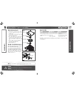
fig 2
Height scale
Indicator
Height-
adjustment
locking knob
fig 3
Angle
guide
plate
Angle scale
Indicator
Angle-adjustment
locking knob
fig 4
Adapter

