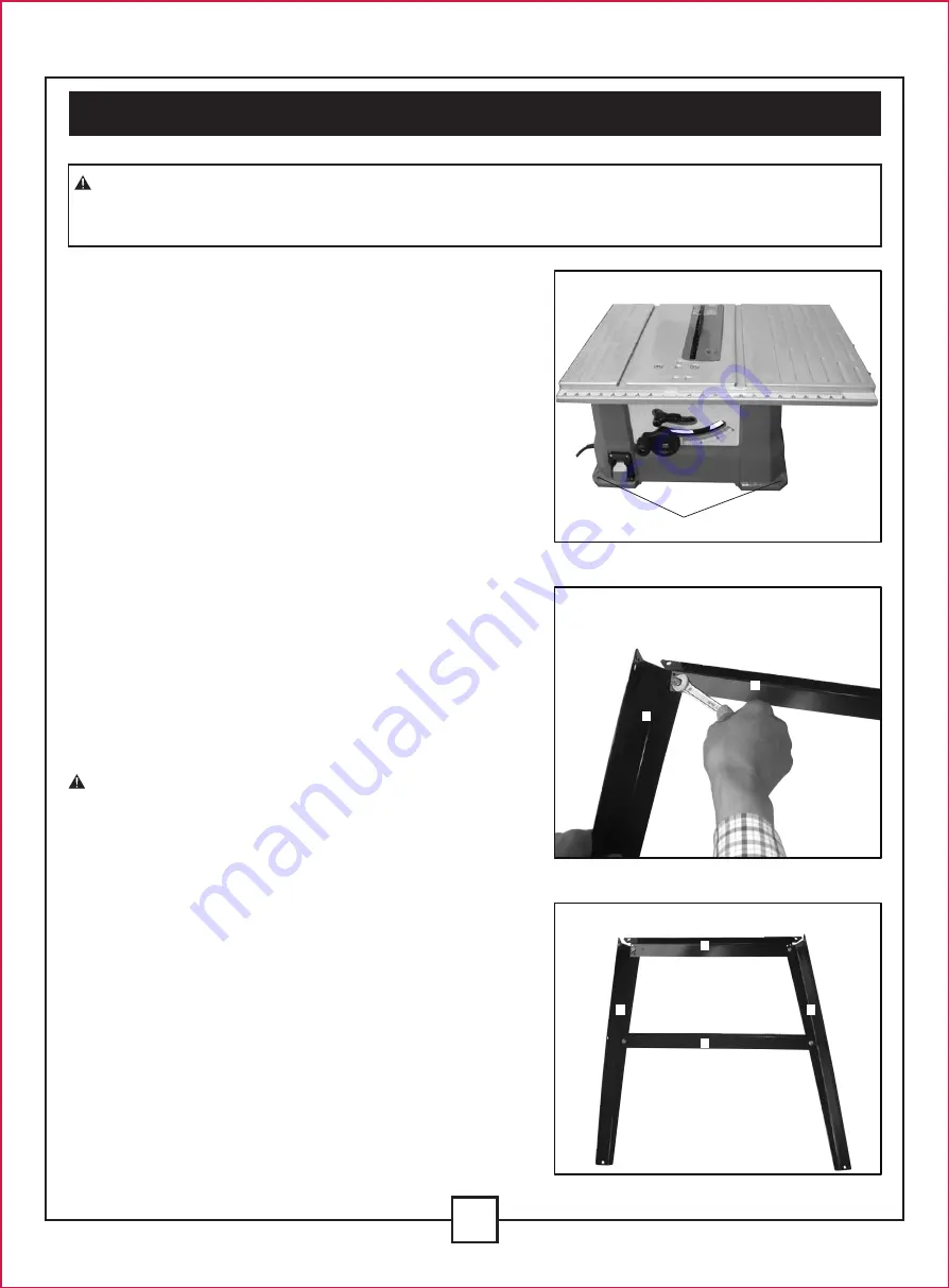
TO ASSEMBLE THE LEG STAND (Fig. 2-5)
1. Unpack all parts, and group them by type and size.
Refer to the parts list for correct quantities, see
Page. 9.
2. Attach one long top leg bracket (B) to the top of one
leg (A) using a screw, flat washer, spring washer and
hex nut. (Fig. 2)
NOTE:
Do not tighten the bolts until the stand is
properly aligned (see step #8).
3. Attach other end of the long top leg bracket (B) to top
of another leg (A) using using a screw, flat washer,
spring washer and hex nut.
4. Attach one long bottom leg bracket (C) to the centre
of each leg (A) using a screw, flat washer, spring
washer and hex nut. This completes the front
frame section. (Fig. 3)
5. Assemble the rear frame section in exactly the same
manner.
6. Join the front and rear frame assemblies to the two
short upper supports (D) and two short bottom
supports (E) using a screw, flat washer, spring washer
and hex nut. (Fig. 4)
7. Insert the rubber foot to the bottom of each leg.
(Fig. 5)
8. Place the stand on a level surface, and adjust it so
WARNING:
DO NOT CONNECT THE PLUG TO THE OUTLET UNTIL ALL INSTALLATIONS
AND ADJUSTMENTS HAVE BEEN COMPLETED AND YOU HAVE READ AND UNDERSTOOD
THE SAFETY AND OPERATIONAL INSTRUCTIONS.
10
MOUNTING HOLES (Fig. 1)
The table saw must be mounted to a firm supporting
surface such as workbench or leg stand. Four bolt
holes have been provided in the saw’s base for this
purpose. Each of the four mounting holes should be
bolted securely using 1/4". machine bolts, lock
washers, and hex nuts (not included). Bolts should be
of sufficient length to accommodate the saw base,
lock washers, hex nuts, and the thickness of the
workbench. Tighten all four bolts securely.
Carefully check the workbench after mounting to
make sure that no movement can occur during use.
If any tipping, sliding, or walking is noted, secure the
workbench to the floor before operating.
V. Assembly and adjustments (continued)
Mounting hole
Fig. 2
Fig. 3
Fig. 1
B
B
C
A
A
A


