background image

OPERA

TING INSTR

UCTIONS

16

AIR

-

POWERED PIN NAILER  058

-

8122

-6

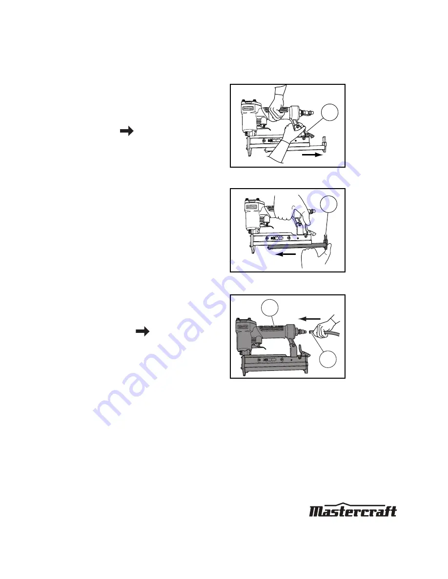
3. Take hold of the nailer firmly with one 

hand and use the other hand to press 
the magazine latch (1) and slide it back. 
Insert a strip of nails into the magazine. 
Ensure the points of the nails are facing 
down 

(fig C)

.              (see nail type 

icon on page 14)

4. Slide the pusher (1) against the nails to

close the magazine until it comes into
contact with the nails and locks into
place 

(fig D)

.

5. Plug in compressor, turn it on, set the 

pressure regulator to 90 psi, attach one 
end of the  air hose to the compressor 
and the other end of the air hose (1) to 
the tool (2) 

(fig E)

.               page 11 

(wood density chart)

6. Use plumber’s tape to avoid air leak. 

Verify that the air pressure is in the 
correct range 

(see section “Technical 

specifications”)

. The tool is now ready 

for use.

MC-588122-05

1

fig C

MC-588122-06

1

fig D

MC-588122-07

fig E

2

1

Summary of Contents for 058-8122-6

Page 1: ...INSTRUCTION MANUAL AIR POWERED PIN NAILER 058 8122 6...

Page 2: ...UICK START GUIDE TECHNICAL SPECIFICATIONS 3 SAFETY GUIDELINES 4 9 KEY PARTS DIAGRAM 10 IMPORTANT INFORMATION 11 13 TYPES OF FASTENERS 14 OPERATING INSTRUCTIONS 15 19 MAINTENANCE 20 21 TROUBLESHOOTING...

Page 3: ......

Page 4: ...to indicate this information Note The word Note is used to inform the reader of something he she needs to know about the tool PERSONAL SAFETY These precautions are intended for the personal safety of...

Page 5: ...t keep the trigger or the safety stand pressed while loading nails Unintentional firing of a nail could cause serious personal injury or death Do not disconnect or reconnect the air hose with the trig...

Page 6: ...the parts to cool down before handling or servicing Keep children away from the compressor at all times Risk of bursting Do not adjust the pressure switch or safety valve for any reason They have been...

Page 7: ...f entry Do not overload the tool Allow the tool to operate at its optimum speed for maximum efficiency Locate the compressor in a well ventilated area for cooling at a minimum of 12 31 cm away from th...

Page 8: ...Verify that all screws are securely tightened For optimal safety and tool performance inspect the tool daily in order to ensure free movement of the trigger safety mechanisms and springs Keep the wor...

Page 9: ...not in use when it is being handed to another person and when it is left unattended Failure to comply may result in moderate injury or damage to equipment Use safety goggles and ear protection Wear s...

Page 10: ...KEY PARTS DIAGRAM 10 AIR POWERED PIN NAILER 058 8122 6 No Description No Description 1 Air inlet plug 4 Magazine 2 Rubber grip 5 Adjustment lever 3 Trigger 6 Exhaust deflector 4 5 1 2 3 6 MC 588122 01...

Page 11: ...grip rubber handle for improved control and comfort even during extended use An adjustment lever automatically adjusts pin length It is best suited for installing door and window trim decorative trim...

Page 12: ...wear WARNING Potential hazard that could result in serious injury or loss of life Keep hands and other parts of the body away from the tool s discharge and working areas when connecting the air supply...

Page 13: ...d this Instruction Manual carefully before using the Air powered Pin Nailer Read and follow all the safety instructions at the beginning of this manual Inspect the Air powered Pin Nailer prior to each...

Page 14: ...are used to select the proper nails for this specific nailer Note Icons are colour coded please refer the actual tool for the specific colour Length 1 2 1 13 to 25 mm WARNING Potential hazard that co...

Page 15: ...l hazard that will result in serious injury or loss of life Disconnect the tool from the compressed air source before loading nails Do not point the tool towards the operator or other people while cha...

Page 16: ...st the nails to close the magazine until it comes into contact with the nails and locks into place fig D 5 Plug in compressor turn it on set the pressure regulator to 90 psi attach one end of the air...

Page 17: ...d successive nails will fire each time the trigger is pulled WARNING Potential hazard that could result in serious injury or loss of life The safety tip must be in contact with the workpiece before ac...

Page 18: ......

Page 19: ...r supply line to the tool s air inlet Test fire 3 to 5 nails into a piece of scrap wood in order to ensure a proper operation Note If the nails continue to jam call 1 800 689 9928 WARNING Potential ha...

Page 20: ...ED DESCRIPTION TOOLS OR MATERIALS REQUIRED MAXIMUM SERVICE INTERVAL Each Use or every 2 Hrs Monthly As Needed General inspection free movement Trigger spring safety mechanism None X In depth inspectio...

Page 21: ...caps frequently in order to help prevent personal injury Inspect the trigger spring and safety mechanism for free movement on a regular basis in order to ensure that the safety system is fully functio...

Page 22: ...of the tool or in the trigger area 1 O rings in the trigger valve are damaged 2 The trigger valve heads are damaged 3 Trigger valve stem seal or O rings are damaged 1 Inspect and replace the O ring 2...

Page 23: ...nternal parts Have the tool serviced by a qualified service technician The tool skips nails 1 The bumper is worn or the spring is damaged 2 There is dirt in the front plate 3 Nails cannot move freely...

Page 24: ...TROUBLESHOOTING 24 AIR POWERED PIN NAILER 058 8122 6...

Page 25: ...AILER 058 8122 6 1 11 12 18 19 20 21 23 25 26 27 29 31 30 34 35 62 28 24 22 13 14 15 16 17 2 3 4 5 6 7 8 9 10 1 36 37 41 42 52 46 47 52 44 45 48 49 42 43 33 32 37 52 51 50 39 40 52 1 38 29 31 58 57 56...

Page 26: ...X 3 1 36 Bolt M4 X 14 2 11 Collar 1 37 Bolt M4 X 7 3 12 O ring 30 2 X 2 65 1 38 Left magazine 1 13 Cylinder 1 39 Adjustment slice 1 14 O ring 18 X 2 65 1 40 Length adjustment bolt 1 15 Main piston 1 4...

Page 27: ...damaged or if you have any questions please call 1 800 689 9928 53 Bracket 1 59 End cap 1 54 Spring 1 60 Air inlet plug cap 1 55 Fixed lever 1 61 Air inlet plug 1 56 Nut M5 1 62 Spring washer 4 2 57...

Page 28: ...ed to fuel lubricants vacuum bags blades belts sandpaper bits fluids tune ups or adjustments e This warranty will not apply where damage is caused by repairs made or attempted by others i e persons no...

Page 29: ...y which shall be covered under the product manufacturer s warranty if any Additional limitations This warranty applies only to the original purchaser and may not be transferred Neither the retailer no...

Reviews: