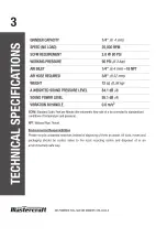
background image

MAINTENANCE

17

AIR-POWERED FULL-SIZE DIE GRINDER  058-9332-0

Air

-

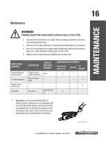
operated tools must be inspected periodically, and worn or broken parts must be replaced 

in order to keep tools operating safely and efficiently.

Inspect and replace worn or damaged O

-

rings, seals, etc. Tighten all screws and caps 

frequently in order to help prevent personal injury.

Loss of power or erratic action may be due to the following
-   Excessive drain in the air line.
-   Moisture or restriction in the air pipe.
-   Incorrect size or type of hose connector. Check the air supply and follow instructions.
-   Grit or gum deposits in the Die Grinder may also reduce performance.

Inspect the trigger, the spring, and the safety mechanism for free movement on a regular 
basis in order to ensure that the safety system is fully functional.

Verify that no part is loose or missing and that no part is stuck or jammed.

Disconnect the tool from the air supply, clean, and store it in a safe, dry, and childproof 
location, when tool is not in use.

When temperatures are below freezing, keep tools as warm as possible using any safe, 
convenient method.

Check the air supply for correct size and type of hose connectors. To avoid loss of power or 
erratic action, ensure that there is no additional drain on the air line and no moisture or 
restriction in the air pipe.

Storage

Apply an ample amount of lubrication before storing the tool.

Run the tool for approximately 30 seconds after lubricating, in order to ensure that the 
lubrication is uniformly distributed throughout the tool.

Store the tool in a clean and dry environment.

Summary of Contents for 058-9312-8

Page 1: ...INSTRUCTION MANUAL AIR POWERED GRAVITY FEED SPRAY GUN 058 9312 8...

Page 2: ...AY GUN 058 9312 8 QUICK START GUIDE TECHNICAL SPECIFICATIONS 2 SAFETY GUIDELINES 3 8 KEY PARTS DIAGRAM 9 IMPORTANT INFORMATION 10 11 OPERATING INSTRUCTIONS 12 16 MAINTENANCE 17 19 TROUBLESHOOTING 20 2...

Page 3: ......

Page 4: ...indicate this information Note The word Note is used to inform the reader of something he she needs to know about the tool PERSONAL SAFETY These precautions are intended for the personal safety of the...

Page 5: ...ically react with aluminium and zinc parts and which is not chemically compatible with aluminium and zinc parts Risk of electric shock Do not expose a compressor to rain Store it indoors Disconnect th...

Page 6: ...er from tank after each use Do not weld or repair tank Relieve all pressure in the hose before removing or attaching accessories Do not use this tool in the presence of flammable liquids or gases Spar...

Page 7: ...ell ventilated area for cooling at a minimum of 12 31 cm away from the nearest wall Protect the air hose and the power cord from damage and puncture Inspect them for weak or worn spots every week and...

Page 8: ......

Page 9: ...spirator to prevent hazards caused by inhaling toxic vapour or contact of solvent and paint with eyes or skin Failure to comply may result in moderate injury Use safety goggles and ear protection Wear...

Page 10: ......

Page 11: ...ft Air powered Gravity feed Spray Gun Using tools or combinations of tools that together or separately require more than the air compressor can deliver will reduce performance and could void the compr...

Page 12: ...N 058 9312 8 CAUTION Potential hazard that may result in moderate injury or damage to equipment Incomplete or improper cleaning could cause function failures and a degradation of the tool Failure to c...

Page 13: ...performed Note Always thin the paint with care WARNING Potential hazard that could result in serious injury or loss of life Do not exceed the maximum pressure for the Air powered Gravity feed Spray Gu...

Page 14: ......

Page 15: ......

Page 16: ......

Page 17: ...direction 1 Uniform coating region 2 Stroke starting position 3 Trigger pressing position 4 Trigger releasing position 5 Stroke stopping position 6 Gun movement path Do not press the trigger with the...

Page 18: ......

Page 19: ......

Page 20: ......

Page 21: ...mmediately Failure to heed this warning could result in serious personal injury PROBLEM POSSIBLE CAUSES SOLUTIONS Fluttering or spitting 1 Paint level is too low 2 Container is tipped too far 3 Fluid...

Page 22: ...pressed 1 Air valve stem is stuck 2 Air valve or seat is contaminated 3 Air valve or seat is worn or damaged 4 Air valve spring is broken 5 Valve stem is bent 1 Lubricate the air valve stem 2 Clean th...

Page 23: ...ther repair information please call 1 800 689 9928 No spray 1 No pressure in gun 2 Fluid control is not properly opened 3 Fluid is too thick or heavy 1 Check air lines 2 Open the fluid control 3 Thin...

Page 24: ......

Page 25: ......

Page 26: ...limited to fuel lubricants vacuum bags blades belts sandpaper bits fluids tune ups or adjustments e This warranty will not apply where damage is caused by repairs made or attempted by others i e pers...

Page 27: ...company which shall be covered under the product manufacturer s warranty if any Additional limitations This warranty applies only to the original purchaser and may not be transferred Neither the retai...

Page 28: ......

Page 29: ......

Page 30: ......

Page 31: ......

Page 32: ......

Page 33: ......

Page 34: ......

Page 35: ......

Page 36: ......

Page 37: ......

Page 38: ......

Page 39: ......

Page 40: ......

Page 41: ......

Page 42: ......

Page 43: ......

Page 44: ......

Page 45: ......

Page 46: ......

Page 47: ......

Page 48: ......

Page 49: ......

Page 50: ......

Page 51: ......

Page 52: ......

Page 53: ......

Page 54: ......

Page 55: ......

Page 56: ......

Page 57: ......

Page 58: ......

Page 59: ......

Page 60: ......

Page 61: ......

Page 62: ......

Page 63: ......

Page 64: ......

Page 65: ......

Page 66: ......

Page 67: ......

Page 68: ......

Page 69: ......

Page 70: ......

Page 71: ......

Page 72: ......

Page 73: ......

Page 74: ......

Page 75: ......

Page 76: ......

Page 77: ...INSTRUCTION MANUAL AIR POWERED FULL SIZE DIE GRINDER 058 9332 0...

Page 78: ...INDER 058 9332 0 QUICK START GUIDE TECHNICAL SPECIFICATIONS 3 SAFETY GUIDELINES 4 9 KEY PARTS DIAGRAM 10 IMPORTANT INFORMATION 11 13 OPERATING INSTRUCTIONS 14 15 MAINTENANCE 16 17 TROUBLESHOOTING 18 1...

Page 79: ......

Page 80: ...hese precautions are intended for the personal safety of the user and others working with the user Please take time to read and understand them DANGER Potential hazard that will result in serious inju...

Page 81: ...er air powered tool Do not use oxygen or any other combustible or bottled gas to power air powered tools Failure to observe this warning can cause explosion and serious personal injury or death Use on...

Page 82: ...temperatures In order to avoid burns or other injuries do not touch the pump the manifold or the transfer tube while the compressor is running Allow the parts to cool down before handling or servicing...

Page 83: ...upply Verify that grinding accessories that are used with this tool are rated at or above the tool s speed rating 25 000 RPM Failure to properly match the accessory to the tool could result in serious...

Page 84: ...orkbench may lead to an accident Floors should be kept clear This tool is not a toy Use it with caution Use the tool in a well ventilated area Verify that the tool has stopped before putting it down a...

Page 85: ......

Page 86: ......

Page 87: ...he compressor can run continuously with the Mastercraft Air powered Full size Die Grinder Using tools or a combination of tools that together or separately require air pressure more than that of which...

Page 88: ......

Page 89: ...e the tool Clean the air inlet and the filter weekly Line pressure should be increased to compensate for unusually long air hoses The hose diameter should be 3 8 WARNING Potential hazard that could re...

Page 90: ......

Page 91: ......

Page 92: ......

Page 93: ...chanism for free movement on a regular basis in order to ensure that the safety system is fully functional Verify that no part is loose or missing and that no part is stuck or jammed Disconnect the to...

Page 94: ...ad 1 Worn or damaged motor parts 2 Cam clutch is worn or stuck due to insufficient lubrication 1 Lubricate clutch housing 2 Check for excess clutch oil as the clutch requires only fifty percent of oil...

Page 95: ...air inlet 2 Operate the tool in forward and or reverse rotation within a short duration 3 Tap motor housing gently with plastic mallet 4 Disconnect the tool from the air supply Operate the motor manu...

Page 96: ......

Page 97: ...3 Chuck screw 1 19 Label 2 1 4 Front grip 1 20 Trigger 1 5 Retainer ring 1 21 Pin 3 X 24 1 6 Bearing 1 22 Muffle cover 1 7 Front plate 1 23 Air inlet plug 1 8 Pin 1 5 X 4 1 24 Label 1 1 9 Pin 2 X 6 2...

Page 98: ...limited to fuel lubricants vacuum bags blades belts sandpaper bits fluids tune ups or adjustments e This warranty will not apply where damage is caused by repairs made or attempted by others i e perso...

Page 99: ...ompany which shall be covered under the product manufacturer s warranty if any Additional limitations This warranty applies only to the original purchaser and may not be transferred Neither the retail...

Reviews: