background image

17

16

model no. 058-9807-2 | contact us 1-800-689-9928

Adjustments

 OPERATING INSTRUCTIONS

 OPERATING INSTRUCTIONS

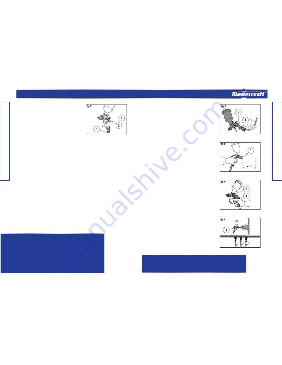
The Gravity-feed Spray Gun has a pattern

adjusting knob (1), a paint adjusting knob (2),

and an air adjusting knob (3) that are used to

obtain the desired pattern, to control the output

volume of paint, and to obtain fine atomization,

respectively (fig E).

PATTERN ADJUSTMENT

Rotate the pattern adjusting knob clockwise to

form a circular spray pattern and rotate the

knob counter-clockwise to form an elliptical

spray pattern.

PAINT ADJUSTMENT

Rotate the paint adjusting knob clockwise to

reduce the output volume of paint and rotate

the knob counter-clockwise to increase the

output volume of paint.

AIR VOLUME ADJUSTMENT

Rotate the air adjusting knob clockwise to

reduce the output volume of air and rotate the

knob counter-clockwise to increase the output

volume of air.

Operation

1. Plug in compressor, turn it on set the

    pressure regulator to 40 PSI, attach one

    end of the air hose to the compressor

    and the other end of the air hose (1) to

    the air tool (2) (fig F).

2. Hold the spray gun (1) so that the nozzle

    is approximately 6 to 12” from the work

    surface, perpendicular to the spraying

    area (fig G).

Note: 

Do some practice sprays while adjusting

the spray pattern and setting up the gun, using

a spare surface (scrap piece of metal).

3. Squeeze the trigger (1) of the spray gun

    (2). Start moving the gun before pressing

    the trigger and release the trigger before

    stopping the gun movement at the end

    of each stroke. This procedure will blend

    each stroke with the next without any

    overlap or unevenness (fig H).

4. Move the spray gun (1) at a constant

    pace in a back and forth parallel

    direction, maintaining a uniform distance

    from the surface to be painted (fig I).

5. Repeat the strokes until a uniform

    coating is formed.

Potential hazard that could result in serious injury or loss of life.

WARNING!

• Do not exceed the maximum pressure for the Air-powered Gravity-feed 

   Spray Gun or any other parts in the compressor system. Failure to comply 

   could lead to serious injury or loss of life.  

• Never aim or spray at yourself or anybody else as this could cause serious 

   injury. Failure to comply could  lead to serious injury or loss of life. 

• After unpacking the tool, inspect it carefully and check thoroughly for 

   any damage that may have occurred during transit. Ensure the tightness 

   of fittings, bolts,  etc., before performing service operation. 

   performed.

NOTE: 

Use a piece of cardboard as a shield to capture 

the loss of spray paint at the ends of the workpiece to 
protect other surfaces from being painted.

Summary of Contents for 058-9807-2

Page 1: ...L IMPORTANT For your own safety read and follow all of the Safety Guidelines and Operating Instructions before operating this air powered gravity feed spray gun Keep this manual for future reference AIR POWERED GRAVITY FEED SPRAY GUN KIT ...

Page 2: ...NTS TABLE OF CONTENTS TECHNICAL SPECIFICATIONS SAFETY GUIDELINES KEY PARTS DIAGRAM TECHNICAL INFORMATION OPERATING INSTRUCTIONS MAINTENANCE TROUBLESHOOTING EXPLODED VIEW PARTS LIST WARRANTY 4 5 10 11 13 19 22 24 25 28 ...

Page 3: ...ual contains information that relates to PROTECTING PERSONAL SAFETY and PREVENTING EQUIPMENT PROBLEMS It is very important to read this manual carefully and understand it thoroughly before using the product The symbols listed below are used to indicate this information FLUID DELIVERY NOZZLE AIR HOSE REQUIRED PAINT VISCOSITY CFM REQUIREMENT AIR INLET PAINT CAPACITY NORMAL AIR PRESSURE WEIGHT MAXIMU...

Page 4: ...ure is set lower than the maximum operating pressure of the tool Before starting the compressor pull the ring on the safety valve to make sure the valve moves freely Drain water from the tank after each use Do not weld nor repair the tank Relieve all pressure in the hose before removing or attaching accessories SAFETY GUIDELINES SAFETY GUIDELINES SAFETY GUIDELINES Potential hazard that will result...

Page 5: ... mist Store in a tightly closed container in a cool dry well ventilated area free from incompatible substances Do not use the tool near or below freezing temperatures as doing so may cause tool failure Do not store the tool in a freezing environment to prevent ice formation on the operating valves of the tool as doing may cause tool failure Use safety goggles and ear protection Wear safety glasses...

Page 6: ...ium duty and intermittent use Heavy duty and continuous use Light duty and intermittent use Medium duty and intermittent use Heavy duty and continuous use Air Compressor Size and Power 1 1 2 2 HP 2 1 2 3 HP 3 HP and more 4 6 Gallons 8 11 Gallons 15 Gallons and more Light duty and intermittent use Light duty and intermittent use Medium duty and intermittent use Light duty and intermittent use Mediu...

Page 7: ...E Before assembly and preparation Do not exceed the maximum pressure for the Air powered Gravity feed Spray Gun or any other parts in the compressor system Never aim or spray at yourself or anybody else Failure to comply could result in serious injury or loss of life CAUTION POTENTIAL HAZARD THAT MAY RESULT IN MODERATE INJURY OR DAMAGE TO EQUIPMENT Do not exceed the thinning recommendations of the...

Page 8: ...e stroke appears to be very thick add a small amount of thinner loss of life lead to serious injury or loss of life lead to serious injury or loss of life After unpacking the tool inspect it carefully and check thoroughly for any damage that may have occurred during transit Ensure the tightness of fittings bolts etc before performing service operation Paint filling Mixing and thinning of paint shou...

Page 9: ...area fig G Note Do some practice sprays while adjusting the spray pattern and setting up the gun using a spare surface scrap piece of metal 3 Squeeze the trigger 1 of the spray gun 2 Start moving the gun before pressing the trigger and release the trigger before stopping the gun movement at the end of each stroke This procedure will blend each stroke with the next without any overlap or unevenness...

Page 10: ... 1 Cover the air cap with a cloth and pull the trigger The air that is blown out of the paint nozzle tip enters the paint passage and cleans the inside of the gun 2 Discard the paint remaining in the canister and add some thinner for washing and blow out the gun 3 Clean the inside and outside of the spray gun 1 with a brush 2 fig A 4 Clean the inside of the paint canister 1 fig B 5 Remove and clea...

Page 11: ...uld damage the holes in the nozzle and cap Never immerse the spray gun completely in solvent Do not use components or parts that are not recommended Failure to comply could result in serious injury or loss of life CAUTION Ensure that the needle is removed before disassembling the nozzle to avoid damage to the nozzle closure housing Failure to comply may result in moderate injury or damage to equip...

Page 12: ...LUTIONS Centre of pattern is too narrow Pattern is not spread uniformly 1 Paint is too thin or not sufficient 2 Atomization air pressure is too high 1 Paint has build up on air cap 2 Fluid nozzle is dirty or worn 1 Clean or replace air cap 2 Clean or replace fluid nozzle 1 Regulate paint viscosity 2 Reduce air pressure Width of spray pattern is too narrow 1 Paint is too thick 2 Atomization air pre...

Page 13: ... Switch seat Foam washer Washer Direction screw Spring Round nut Fluid cap washer Atomization Fluid nozzle Fluid nozzle joint Washer Joint washer Direction screw Seal washer Samll washer 1 1 1 2 1 1 1 1 1 1 1 1 2 1 1 1 1 1 1 1 1 1 1 1 1 26 27 28 29 30 31 32 33 34 35 36 37 38 39 40 41 42 43 44 45 46 47 48 Spring Big washer Trigger pin I Trigger pin II Trigger Snap retainer Trigger washer Ventilator...

Page 14: ...d nut Air cap washer Atomization Nut housing O ring 17 X 1 5 Fluid nozzle Fluid nozzle washer Screw Needle washer 1 1 1 2 1 1 1 1 1 1 1 2 1 1 1 1 1 1 1 1 1 1 23 24 25 26 27 28 29 30 31 32 33 34 35 36 37 38 39 40 41 42 43 44 Sealing washer Nut compressed spring Trigger level II Trigger level I Trigger Snap retainer Canister cover Canister Filter Fluid inlet joint Needle Spring Paint adjusting joint...

Page 15: ...mable items such as but not limited to fuel lubricants vacuum bags blades belts sandpaper bits fluids tune ups or adjustments This warranty will not apply where damage is caused by repairs made or attempted by others i e persons not authorized by the manufacturer This warranty will not apply to any product that was sold to the original purchaser as a reconditioned or refurbished product unless oth...

Reviews: