background image


OPERATING MANUAL


COMPOUND MITRE SAW WITH LASER LINE 


55-6857-6 


Parts missing or damaged? Questions? Toll-Free Help Line – 1-800-689-9928 


IMPORTANT: 

Read through this operating manual carefully before using this tool. Pay close 
attention to all 

Safety Instructions, Warnings

 and 

Caution sections.

 Use this tool 

properly and only for its intended use. 


Safety symbols in this manual are used to call attention to possible dangers. 

The safety symbols and their explanations require your full understanding. The safety 
warnings do not, by themselves, eliminate any danger, nor are they substitute for 
proper accident prevention measures.   


This Safety Alert Symbol indicates caution, warning, or danger. Failure to obey 

a safety warning can result in serious injury to yourself or others. To reduce the risk of 
injury, fire, or electric shock, always follow the safety precautions.   


1

Summary of Contents for 55-6857-6

Page 1: ...s intended use Safety symbols in this manual are used to call attention to possible dangers The safety symbols and their explanations require your full understanding The safety warnings do not by themselves eliminate any danger nor are they substitute for proper accident prevention measures This Safety Alert Symbol indicates caution warning or danger Failure to obey a safety warning can result in ...

Page 2: ...TIONS Specifications Motor 120 V 60Hz 9 A Speed 5 000 RPM no load Blade size 7 1 4 18 4 cm 40 tooth carbide tipped Laser Class llla Laser Product Complies with 21 CFR parts 1040 10 and 1040 11 Laser wavelength 635 655 nm Laser output 2 5 mW Bore size 5 8 15 9mm Weight 17 lb 3 oz 7 8kg Cutting capacity 2 x 4 1 8 straight at 90 mitre 0 bevel 2 x 2 9 16 mitre at 90 mitre 45 bevel 1 1 4 x 4 1 8 bevel ...

Page 3: ...its designed rate Only use the correct tool Do not force the tool or an attachment to do a job that it was not designed to perform Use proper extension cords Make sure extension cords are in good condition When using an extension cord be sure to use a cord heavy enough to carry the drawn current needed by the compound mitre saw An undersized cord will result in a drop in line voltage and in loss o...

Page 4: ...er leave the tool unattended while the power is on Turn the power off Do not leave the tool until the blade comes to a complete stop and the mitre saw is unplugged Do not over reach Keep proper footing and balance at all times Maintain tools with care Keep tools sharp and clean for optimum performance Follow instructions for lubricating and changing accessories CAUTION Do not attempt to operate th...

Page 5: ...h a 9 A time delay fuse or circuit breaker Using the wrong size fuse can damage the motor IF the motor won t start release the ON OFF trigger switch immediately UNPLUG THE SAW Check the saw blade to make sure it turns freely If the blade is free try to start the saw again If the motor still does not start refer to the TROUBLESHOOTING GUIDE IF the tool suddenly stalls while cutting wood release the...

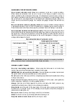
Page 6: ...otal length of cord in feet Volts Cord size in A W G minimum Tool s Ampere rating 25 50 100 150 0 6 18 16 16 14 6 10 18 16 14 12 120 V 10 12 16 16 14 12 12 16 14 12 not recommended WARNING Ensure the power supply outlet in question is properly grounded If you are not sure have a licensed electrician check the outlet SPECIFIC SAFETY RULES Use only crosscutting saw blades When using the mitre saw to...

Page 7: ...g or securing the work piece changing the work piece angle or changing the angle of the blade Never cut ferrous metals or masonry products with this tool This mitre saw is designed for use on wood and wood like products Never cut small pieces Keep your hands outside the no hands zone at least 3 from blade Provide adequate support to the sides of the mitre table for long work pieces Never use the m...

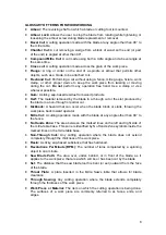
Page 8: ...ar on the end of a spindle or arbour that permits other objects such as a blade to be attached to it Freehand Cut Performing a cut without using a fence mitre gauge fixture work clamp or other pro during the cut Do not perform any operation free ha wherever possible Gum A sticky sap based residue from w Kerf The material removed by the blade in a through cut or the slot produced by the blade in a ...

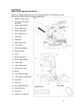
Page 9: ...er blade guard 5 Blade screw guard 6 Dust extraction port 7 Saw blade 8 Mitre table 9 Mitre angle scale 10 Throat plate 11 Mitre angle indicator 12 Mounting holes 13 Fence 14 Bevel angle scale 15 Bevel angle indicator 16 Laser guide 17 Lower blade guard 18 Spindle lock button 19 Brush 20 Laser ON OFF switch 21 Laser battery compartment 22 Stop latch 23 Mitre lock 24 Bevel adjusting screw Saw Blade...

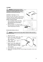
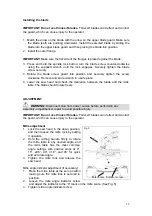
Page 10: ...stop latch to lock down the saw head for transporting and storage Removing the blade see Fig 4 WARNING To reduce the risk of injury always unplug tool before removing and installing a blade 1 Raise the saw head 2 Loosen but do not remove the screw on the blade screw guard Fig 1 point 5 counter clockwise with a screwdriver 3 Rotate blade screw guard to expose blade screw 4 Press and hold the spindl...

Page 11: ...nce between the blade and the mitre table The blade should rotate freely ADJUSTMENT WARNING Disconnect plug from power source before performing any assembly adjustment or repair to avoid possible injury IMPORTANT Do not use thin kerf blades Thin kerf blades can deflect and contact the guard which can cause injury to the operator Mitre adjustment Fig 5 1 Lock the saw head in the down position and t...

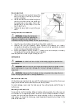
Page 12: ...tery cover in position Note Replacement AAA require a rating of 1 5V OPERATION WARNING To reduce the risk of injury wear safety goggles or glasses with side shields WARNING Before each use check that the blade is free from cracks loosen teeth missing teeth or any other damage Do not use if damage is noticed or suspected WARNING Always wait for the blade to stop completely and unplug the tool befor...

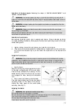
Page 13: ...s only if you are under the supervision of an experienced person Support of work piece WARNING Never use the help of another person as a substitute for a table extension as an additional support for a work piece that is longer or wider than the basic mitre table Never have another person help feed support or pull the work piece in place of table extensions Use the fence Align the work piece flush ...

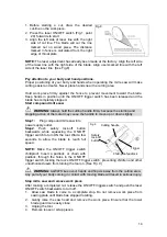
Page 14: ... stopping action of the motor may cause the handle to move up or down slightly Step1 Plug compound mitre saw into power supply outlet Fig 9 Step2 Push safety lock off button backwards while squeezing the ON OFF trigger switch to turn ON the tool Wait a few seconds to allow the blade to reach full speed NOTE Make the ON OFF trigger switch childproof Insert a padlock or chain with padlock through th...

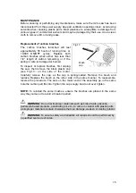
Page 15: ... first unplug the saw then remove the black plastic cap see Fig 10 on the side of the motor Carefully remove the cap as the cap is spring loaded Remove the brush and replace Replace the brush on the other side in the same manner To reassemble reverse the procedure The ears on the metal end of the assembly go in the same hole the carbon part fits into Tighten the cap snugly but do not over tighten ...

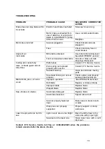
Page 16: ...rvice Contact CTC Service Centre raise or blade guard cannot fully close Sawdust build up Clean and lubricate moving parts Saw head locking pin not set properly Check adjust and properly set saw head locking pin Improper operation See OPERATION section Blade binds jams or burns Dull blade Replace or sharpen blade wood Improper blade Replace blade Warped blade Replace blade Saw blade damaged Replac...

Page 17: ...17 ...

Page 18: ...n Washer 1 70 L 04 340201A1 Blade Cover 1 117 T 12 434401T Switch 1 23 T 02 06014312 Hexagon Socket Screw 2 71 L 06 340223A1 Rivet 1 118 T 09 110173A Ball Bearing 1 24 T 03 0601021 Hexagon Nut 2 72 T 02 15008211 Screw 1 119 L 07 340203B1 Rotor 1 25 T 02 64006311 Slotted Set Screw 1 73 L 06 340203A1 Bolt 1 120 T 09 108213A Ball Bearing 1 26 L 06 340208A1 Shaft 1 74 L 06 340202A1 Outer Flange 1 121 ...

Page 19: ...ades belts sandpaper bits fluids tune ups or adjustments e this warranty will not apply where damage is caused by repairs made or attempted by others i e persons not authorized by the manufacturer f this warranty will not apply to any product that was sold to the original purchaser as a reconditioned or refurbished product unless otherwise specified in writing g this warranty will not apply to any...

Reviews: