Installing the blade
IMPORTANT: Do not use thin-kerf blades.
Thin-kerf blades can deflect and contact
the guard, which can cause injury to the operator.
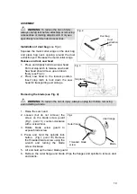
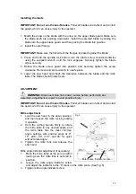
1. Match the arrow on the blade with the arrow on the upper blade guard. Make sure
the blade teeth are pointing downward. Install the selected blade by sliding the
blade into the upper blade guard and then placing the blade into position.
2. Install the outer flange.
IMPORTANT:
Make sure the flat side of the flanges is placed against the blade.
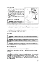
3. Press and hold the spindle lock button, turn the blade screw counter-clockwise
using the supplied wrench until the lock engages. Securely tighten the blade
screw securely.
4. Rotate the blade screw guard into position and securely tighten the screw
clockwise. Remove and store wrench in a safe place.
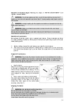
5. Lower the saw head and check the clearance between the blade and the mitre
table. The blade should rotate freely.
ADJUSTMENT
WARNING:
Disconnect plug from power source before performing any
assembly, adjustment or repair to avoid possible injury.
IMPORTANT: Do not use thin-kerf blades.
Thin-kerf blades can deflect and contact
the guard, which can cause injury to the operator.
Mitre adjustment
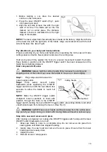
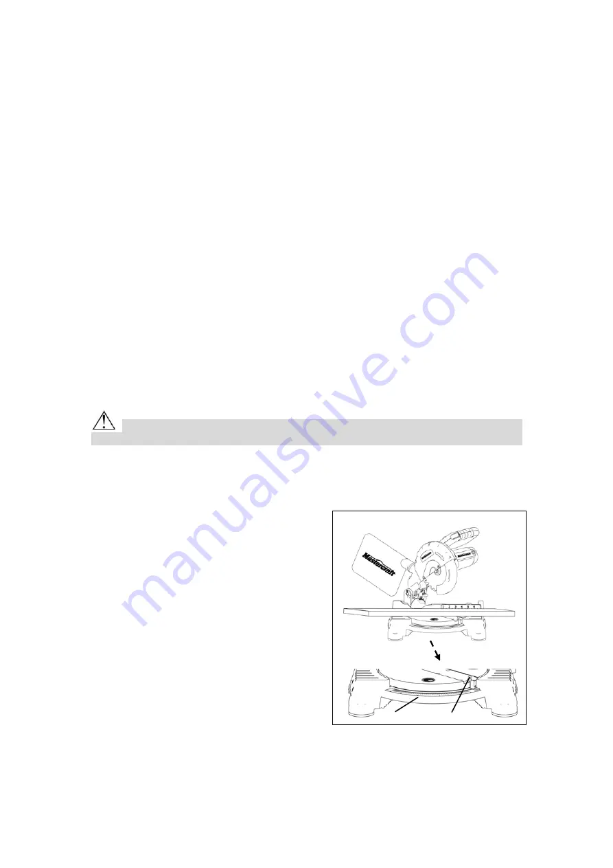
Fig.5
1. Lock the saw head in the down position,
and then loosen the mitre lock by pulling
it upwards.
2. Hold the cutting handle firmly to rotate
the mitre table to any desired angle, and
the mitre table has the most common
angle settings with positive stops at 0°,
15°, 22.5°, 30°, 31.6°, and 45° for quick
and accurate angle.
3. Tighten the mitre lock and release the
saw head.
Mitre angle indicator adjustment (if necessary)
1. Place the mitre table at the zero position
making sure the mitre lock is secured in
position.
2. Loosen the mitre angle indicator screw
and adjust the indicator to the “0” mark on the mitre scale. (See Fig. 5)
3. Tighten mitre angle indicator screw.
Miter scale Indicator screw
11
Summary of Contents for 55-6857-6
Page 17: ...17 ...


