background image

17

16

model no. 054-1232-4  |  contact us 1.800.689.9928

ASSeMbLY INSTRUCTIONS

ATTAChINg The TOP hANdLe TO 
The ORbITAL JIgSAw (fig 7)

1.  Align and slide the rear bottom of the 

top handle with the attaching plate 
compartment.

2.  Slide the top handle onto the attaching 

plate compartment, and hold down the 
handle-release buttons until the top 
handle snaps and locks into place (fig 7).

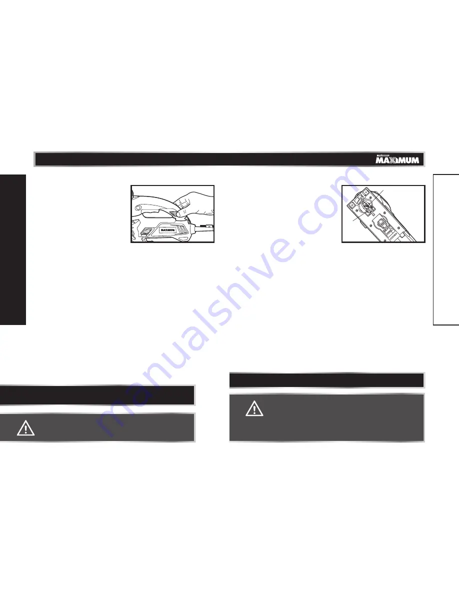
TOOL-LeSS bLAde INSTALLATION (fig 8)

The tool-less blade change control allows 
you to remove and replace the saw blade 
quickly and easily, without the use of 
additional tools.

1.  Unplug the saw.

2.  Raise the clear chip shield, lift one side 

of its mounting slot, and remove the 
shield from the saw. Apply slight force 
when lifting and removing the shield 
from the saw.

3.  Turn the saw upside down so that you can access the blade clamp.

4.  Depress the tool-less blade-change lever. Insert the blade directly into the 

slot of the tool-less blade change holder (fig 8). The teeth of the blade should 
be facing the front and pointing up (when saw is right side up, in cutting 
position), and the back of the blade must rest in the groove of the blade 
guide rollers.

5.  Pull the blade to make sure it is securely locked in place.

A

S

S

e

M

b

LY INS

TRUCTIONS

CAUTION!

•  Once the blade is installed in the saw, it is always exposed. There 

is no lower blade guard. Use caution when handling the saw so 
that the blade does not catch clothing, skin, etc. Each time you 
set the saw down, take care not to bend the blade. Always set 
the saw down on its side when the blade is installed. Always 
remove the blade when saw is not being used.

FPO

wARNINg!

•  Make sure the push-on switch is OFF when attaching the top 

handle to the orbital jigsaw.

FPO

fig 7

NOTe:


The push-on switch cannot be switched on when the top handle is on 

the orbital jigsaw.

NOTe:


For use with both “T” &”U” shanked blades.

A

S

S

e

M

b

LY INS

TRUCTIONS

fig 8

Blade

Blade 
Guide 
Rollers

Summary of Contents for MAXIMUM 054-1232-4

Page 1: ...INSTRUCTION MANUAL IMPORTANT Read and understand this instruction manual thoroughly before using the product model no 054 1232 4 Orbital Jigsaw with Laser Line and 360 Scroll Cutting ...

Page 2: ...ions 22 28 Maintenance 29 Troubleshooting 30 Part list 31 33 Warranty 34 35 NOTE If any parts are missing or damaged or if you have any questions please call our toll free helpline at 1 800 689 9928 SAVE THESE INSTRUCTIONS This manual contains important safety and operating instructions Read all instructions and follow them with use of this product TABLE OF CONTENTS ...

Page 3: ...efers to your mains operated corded power tool or battery operated cordless power tool Work area safety Keep the work area clean and well lit Cluttered or dark areas invite accidents Do not operate power tools in explosive atmospheres such as in the presence of flammable liquids gases or dust Power tools create sparks which may ignite the dust or fumes Keep children and bystanders away while opera...

Page 4: ... and or the battery pack from the power tool before making any adjustments changing accessories or storing power tools Such preventive safety measures reduce the risk of starting the power tool accidentally Store idle power tools out of the reach of children and do not allow persons unfamiliar with the power tool or these instructions to operate the power tool Power tools are dangerous in the hand...

Page 5: ...rom this device should never be directed toward any person for any reason Be sure the laser beam is aimed at a workpiece such as wood or rough coated surfaces that does not have a reflective surface Do not use on surfaces like sheet steel that have a shiny reflective surface The shiny surface may reflect the beam back at the operator Be aware that laser light reflected off a mirror or any other re...

Page 6: ...wrench 16 Top handle 6 Push on switch 17 Edge guide 7 Blade storage 18 Live tool indicator LED light 8 Bevel angle scale 19 Edge guide mounting slot 9 Locking knob for edge guide 20 Base plate 10 Blade guide 21 Laser aperture 11 Laser on off button KEY PARTS DIAGRAM WARNING Remove the orbital jigsaw from the package and examine it carefully Do not discard the carton or any packaging material until...

Page 7: ...sawdust removal system Push the vacuum blower knob to blow debris away from the cutting area or attach the vacuum adapter fig 2 to a wet dry vac hose with a 1 1 2 38 mm adapter all sold separately 1 Unplug the saw 2 Switch the vacuum blower knob to the BLOWER position in order to blow sawdust metal and plastic chips away from the cutting area 3 Switch the vacuum blower knob fig 3 to the VACUUM pos...

Page 8: ...soft woods SCROLLING CONTROL KNOB fig 6 The scrolling feature allows the blade to be rotated 360 It is ideal for cutting curves designs and detailed pattern work 1 To engage the scrolling function move the scrolling orbit control lever to the SCROLLING position fig 5 2 Grasp the scrolling control knob fig 6 3 The scrolling control knob can be rotated 360 to the left or right while guiding the saw ...

Page 9: ...de change lever Insert the blade directly into the slot of the tool less blade change holder fig 8 The teeth of the blade should be facing the front and pointing up when saw is right side up in cutting position and the back of the blade must rest in the groove of the blade guide rollers 5 Pull the blade to make sure it is securely locked in place ASSEMBLY INSTRUCTIONS CAUTION Once the blade is ins...

Page 10: ...m undue wear 1 The variable speed dial is used to adjust the speed of the blade 2 Turn the dial to increase or decrease the speed of the blade fig 10 3 Position 1 selects the slowest blade speed position 6 selects the fastest blade speed Adjust blade speed for optimum performance Workpiece to be cut Number on the variable speed dial Wood 5 6 Mild steel 2 5 Stainless steel 3 4 Aluminium 3 6 Plastic...

Page 11: ... of the edge guide through the slots in the base of the orbital jigsaw It can be inserted from either side of the base with the edge guide facing down 2 Screw the edge guide locking knob into the threaded hole in the base in order to tighten the edge guide bar in place 3 Measure the distance from the edge of the workpiece to the cutting line Slide the edge guide to this desired distance and tighte...

Page 12: ...re is convenient for continuous sawing applications 5 To release the lock on button press and release the trigger switch USING THE LASER LIGHT FEATURE fig 17 Your orbital jigsaw has a built in laser light To activate the laser plug in your orbital jigsaw and press the laser ON OFF button 1 Mark the cutting line on the workpiece 2 Adjust the cutting angle and cutting speed as needed 3 Plug in the s...

Page 13: ...utting blade Be extremely careful to move the saw very slowly as you cut Use the low speeds position 1 2 or 3 on the variable speed dial Also use the LOW position on the orbital control lever Do not twist bend or force the blade If the saw jumps or bounces as you cut change to a blade with finer teeth If the blade begins to clog when cutting soft metal change to a blade with coarser teeth For easi...

Page 14: ...ly holding the toe of the saw base in order to prevent side wobble 5 Slowly pivot the saw downward as if on a hinge until the blade cuts through and the base rests flat on the workpiece 6 Begin sawing along the cutting line in the usual manner MAKING SHARP CORNERS 1 Cut up to the corner and then back up slightly before rounding the corner 2 After the opening is complete go back to each corner and ...

Page 15: ... vibration or noise occurs turn the saw off immediately and have the problem corrected before further use Unplug the saw from the socket before cleaning or performing any maintenance Using compressed air may be the most effective cleaning method Always wear safety goggles when cleaning tools using compressed air If the power cord is damaged it must be replaced with an identical replacement part an...

Page 16: ...ng glasses available separately LED worklight does not light The tool isn t plunged in Make sure the tool is plugged in The scrolling control cannot be turned The Orbit Scrolling lever is not in the Scrolling position Set the lever in the Scrolling position If the problem remains unsolved after performing the checks described above call the toll free helpline at 1 800 689 9928 Exploded View WARNIN...

Page 17: ...0000 Tapping Screw 53 5700030000 Needle Bearing 27 2822669000 Link Assembly 54 3700203000 Washer 1 No Part No Description No Part No Description 55 3520058000 Pendulum Plate 80 3660055000 Carbon brush Spring 56 3700224000 Counterweight A 81 4870043000 Switch 57 3700225000 Counterweight 82 4890524000 PCB Assembly 58 3700226000 Washer 83 4930004000 Connecter 59 3700184000 Washer D 84 3123861000 Left...

Page 18: ... after a reasonable period of use d This warranty will not apply to routine maintenance and consumable items including but not limited to fuel lubricants vacuum bags blades belts sandpaper bits fluids tune ups or adjustments e This warranty will not apply where damage is caused by repairs made or attempted by others i e persons not authorized by the manufacturer f This warranty will not apply to a...

Page 19: ......

Reviews: