background image

10

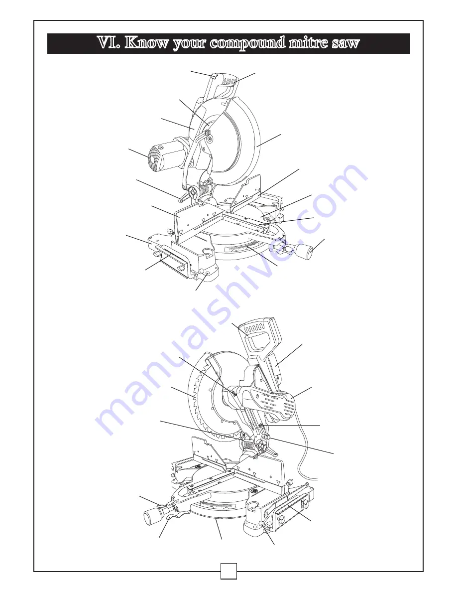
VI. Know your compound mitre saw

Table 

Mounting Hole

Switch Handle

Motor

Lower Blade Guard

Mitre Handle

Mitre Scale

Upper Blade Guard

Cover Plate

Sliding Fence

Safety lock-off switch

Left Extension Bracket

Base

Table Insert

Bevel Lock Handle

Arbor Lock

Stop Latch Knob

Positive Stop Locking Lever

Saw Blade

Positive Mitre Detents

Extension Table Lock Knob

Right Extension Bracket

ON/OFF Trigger Switch

Carry Handle

Belt Cover

Quick-cam Mitre Table Lock

Laser ON/OFF Switch

Fence

Hawkeye Laser

®

Summary of Contents for Maximum Hawkeye Laser 055-6746-0

Page 1: ...1 Dual beveling Compound Mitre Saw 055 6746 0 Owner s Manual Toll Free Helpline 1 800 689 9928 MD R ...

Page 2: ...EED 3800 RPM no load BLADE 12 30 5 cm 40 tooth carbide tipped ARBOR DIAMETER 5 8 15 9 mm LASER Class IIIa LASER WAVELENGTH 630 660 nm LASER OUTPOWER 5 mW CUTTING CAPACITY 3 x 7 7 8 7 8 x 20 cm crosscut at 0 mitre 0 bevel 3 1 2 x 5 1 2 9 x 14 cm crosscut at 0 mitre 0 bevel 3 x 5 1 2 7 8 x 14 cm mitre at 45 mitre 0 bevel 3 1 2 x 3 1 2 9 x 9 cm mitre at 45 mitre 0 bevel 1 7 8 x 7 7 8 4 8 x 20 cm beve...

Page 3: ...uld result in death or serious injury if it is not avoided CAUTION indicates a potentially hazardous situation that may result in minor or moderate injury if it is not avoided CAUTION used without the safety alert symbol indicates a potentially hazardous situation that may result in property damage if it is not avoided DANGER WARNING WARNING ICONS Your power tool and its Owner s Manual may contain...

Page 4: ... FROM the work area especially when the tool is operating DO NOT allow children near the tool 6 DO NOT FORCE THE TOOL to do a job that it was not designed to do 7 DRESS FOR SAFETY DO NOT wear loose clothing gloves neckties or jewellery rings watches etc when operating this tool These items can get caught in moving parts and draw the operator in WEAR non slip footwear and tie back long hair 8 WEAR ...

Page 5: ... properly repaired or replaced before use 18 MAKE THE WORKSHOP CHILDPROOF Use padlocks and master switches and ALWAYS remove starter keys 19 DO NOT operate the tool while under the influence of drugs alcohol or medication that may affect your ability to use the tool properly 20 WHEN SERVICING USE ONLY IDENTICAL REPLACEMENT PARTS 21 DO NOT ALLOW ANYONE WHO HAS NOT CAREFULLY READ AND FULLY UNDERSTOOD...

Page 6: ... workpiece should be clamped in place before making the cut 6 BE SURE the blade is sharp runs freely and is free of vibration 7 ALLOW the motor to come up to full speed before starting cut 8 KEEP THE MOTOR AIR SLOTS CLEAN and free of chips or dust 9 ALWAYS MAKE SURE all handles are tight before cutting even if the table is positioned in one of the positive stops 10 BE SURE blade and collar are cle...

Page 7: ...pieces 26 NEVER use the mitre saw in an area where flammable liquids or gases are present 27 NEVER use solvents to clean plastic parts Solvents may dissolve or otherwise damage the material 28 SHUT OFF and disconnect the power before servicing or adjusting the tool 29 DISCONNECT the saw from the power source and clean the machine before leaving it 30 MAKE SURE the work area is clean before leaving ...

Page 8: ...trician IMPROPER CONNECTION of the equipment grounding conductor can result in risk of electric shock The conductor with the green insulation with or without yellow stripes is the equipment grounding conductor If repair or replacement of the electrical cord or plug is necessary do not connect the equipment grounding conductor to a live terminal CHECK with a qualified electrician or service person i...

Page 9: ...essive heat and damp or wet areas Use a separate electrical circuit for your tool This circuit must not be less than 12 wire with a 20 A time lag fuse or a 14 wire with a 15 A time lag fuse NOTE When using an extension cord on a circuit with a 14 wire the extension cord must not exceed 25 in length Before connecting the motor to the power line make sure the switch is in the off position and the el...

Page 10: ...e Sliding Fence Safety lock off switch Left Extension Bracket Base Table Insert Bevel Lock Handle Arbor Lock Stop Latch Knob Positive Stop Locking Lever Saw Blade Positive Mitre Detents Extension Table Lock Knob Right Extension Bracket ON OFF Trigger Switch Carry Handle Belt Cover Quick cam Mitre Table Lock Laser ON OFF Switch Fence Hawkeye Laser ...

Page 11: ...OTECTION Goggles or spectacles intended to protect your eyes Eye protection should meet the requirements of ANSI Z 87 1 USA or CSA Z94 3 M88 Canada FACE SHIELD An impact resistant shield that helps to protect your face from chips sparks and small debris Should only be used in conjunction with additional eye protection FENCE Helps to keep the workpiece from moving when sawing Scaled to assist with ...

Page 12: ...ice to prevent the workpiece from twisting during the cutting operation HEEL Misalignment of the blade KERF The width of a saw cut determined by the thickness and set of the blade KICKBACK Sudden and unintended movement of the tool or workpiece It is typically caused by binding or pinching of the workpiece MITRE CUT A mitre is a type of joint where the two parts to be joined are cut at an angle an...

Page 13: ...gainst the parts listed below Examine all of the parts carefully WARNING If any part is missing or damaged do not plug the mitre saw in until the missing or damaged part has been repaired or replaced For more information call the toll free helpline at 1 800 689 9928 Blade Wrench Mitre Handle Mitre Saw Dust Bag Hold down Clamp AAA Batteries Extension Wings ...

Page 14: ...l out the stop latch knob 2 3 Allow the cutting head to rise to the up position Locking When transporting or storing the mitre saw the cutting head should always be locked in the down position 1 Push the cutting head down to its lowest position 2 Push the stop latch knob 2 into the locking hole Fig 2 WARNING To avoid injury and damage to the saw transport or store the mitre saw with the cutting he...

Page 15: ...ust port Open zipper on underside of bag and empty into waste container 1 2 3 NOTE Check frequently and empty bag before it gets full INSTALLING THE EXTENSION WING ASSEMBLY FIG 4 1 Insert the extension wing bars 1 into the holes 2 in the base 2 Thread one extension wing stop screw 4 into the end of the rear extension wing bar 1 Verify that the screw is fully threaded into the corresponding hole in...

Page 16: ...er 1 2 Insert the two supplied AAA batteries in the case as per the diagram below If replacing the batteries take out the old batteries and place with new AAA batteries Dispose of old batteries properly 3 Close the battery cover 1 NOTE Replace the batteries with batteries that have a rating of 1 5 V Number 4 series and AAA size or equivalent 1 2 2 INSERTING AND REPLACING THE LASER BATTERIES FIG 7 ...

Page 17: ...elow the mitre saw switch handle 7 Press the arbor lock holding it in firmly while turning the blade wrench clockwise The arbor lock will engage after turning the wrench Continue to hold the arbor lock to keep it engaged while turning the wrench clockwise to loosen the arbor bolt 8 Remove the arbor bolt washer 4 outer blade collar 6 and the blade 7 Do not remove the inner blade collar Fig 11 NOTE P...

Page 18: ...e arbor lock in while tightening the arbor bolt securely Fig 10 5 Rotate the cover plate 3 back to its original position until the slot in the cover plate engages with the cover plate screw 2 While holding the lower blade guard tighten the screw with a star head screwdriver Fig 8 9 NOTE The lower blade guard must be raised to the upright position to access the cover plate screw 6 Lower the blade g...

Page 19: ...the fastening method shown in Fig 12 2 For portable use place the saw on a 3 4 19 mm thick piece of plywood Bolt the base of the mitre saw securely to the plywood using the mounting holes on the base Use C clamps to clamp this mounting board to a stable work surface at the worksite Fig 13 Fig 12 Fig 13 2 3 4 1 5 6 7 8 9 1 Mitre saw base 2 Hex head bolt 3 Rubber washer 4 Flat washer 5 Workbench 6 F...

Page 20: ... bevel lock handle 1 tilt the cutting head completely to the left loosen the lock nut 3 on the bevel angle adjustment bolt 4 and adjust the bolt 4 in or out to increase or decrease the bevel angle with a 10 mm wrench 4 Tilt the cutting arm to back to the right at 90 0 bevel and recheck for alignment 5 Repeat steps 1 through 4 if further adjustment is needed 6 Tighten the bevel lock handle 1 and lo...

Page 21: ...the cutting arm back to the right and recheck alignment 7 Repeat steps until the blade is 45 to the table Once alignment is achieved tighten the locknut 3 to secure the positive stop bolt 2 3 4 45 Left Bevel Positive Stop Adjustment Fig 18 1 Loosen the bevel lock handle 1 and set saw arm at 45 angle 2 Set the stop block at 45 position by turning the lever 2 counterclockwise 3 Tilt the cutting arm ...

Page 22: ...nued 33 9 Right Bevel Adjustment Fig 19 1 Set the mitre angle to 0 Fully extend both sliding fences 2 Loosen the bevel lock handle 1 3 Set the stop block 2 at 33 9 position by turning the lever 3 clockwise 4 Using a combination square check to see if the blade is 33 9 to the table 5 If the blade is not 33 9 to the mitre table tilt the cutting arm to the left loosen the locknut 4 on the stop block ...

Page 23: ...TRE ANGLE ADJUSTMENT FIG 22 23 The mitre saw scale can be easily read showing mitre angles from 0 to 45 to the left and right The most common angle cut setting slots have positive stops permitting fast adjustments to the desired position Follow the process below for quickest and most accurate adjustments 1 Lift up on the mitre quick lock lever 1 to unlock the table 2 Move the turntable while lifti...

Page 24: ...holding the positive stop locking lever up grasp the mitre handle and move the mitre table left or right to the desired angle 3 Release the positive stop locking lever 2 4 Press down on the mitre quick cam locking lever 1 until it locks the mitre table in place NOTE The mitre quick cam locking lever should lock the table and prevent it from moving If adjustment is needed see next step QUICK CAM MI...

Page 25: ... mitre saw works WARNING To avoid mistakes that could cause serious permanent injury do not plug the tool in until the following steps are completed Completely assemble and adjust the saw following the instructions assembly and adjustments Learn the use and function of the on off switch lock off switch upper and lower blade guards stop latch bevel lock handle and cover plate screws Review and unde...

Page 26: ... aligned With the saw unplugged push the cutting arm all the way down Manually spin the blade and check for clearance Tilt the cutting arm to a 45 bevel and repeat the test Make sure the blade and arbor collars are clean Make sure all clamps and locks are tight and there is no excessive play in any parts KEEP YOUR WORK AREA CLEAN Cluttered areas and benches invite accidents PLAN YOUR WORK Use the ...

Page 27: ...ward operations and hand positions A sudden slip could cause your fingers or hand to move into the blade DO NOT OVERREACH Keep good footing and balance Keep your face and body to one side out of the line of a possible kickback NEVER stand in the line of the blade Never cut freehand Brace your workpiece firmly against the fence and table stop so it will not rock or twist during the cut Make sure ther...

Page 28: ...se possible injury Moulding for example must lie flat or be held by a fixture or jig that will not let it move when cut Properly support round material such as dowel rods or tubing which have a tendency to roll when cut causing the blade to bite WHEN SAW IS RUNNING WARNING To avoid injury follow all applicable safety instructions when cutting non ferrous metals Use only saw blades specifically recomm...

Page 29: ... Hold workpiece firmly against the fence to prevent movement toward the blade With the power switch OFF bring the saw blade down to the workpiece to see the cutting path of the blade Squeeze trigger switch to start saw Lower blade into workpiece with a firm downward motion Finishing a cut Hold the cutting arm in the down position Release trigger switch and wait for all moving parts to stop before mo...

Page 30: ...ED ON AVOID DIRECT EYE CONTACT ALWAYS UNPLUG THE MITRE SAW FROM POWER SOURCE BEFORE MAKING ANY ADJUSTMENTS NOTE All the adjustments for the operation of this machine have been completed at the factory THE LASER BEAM THE LASER GUIDE FIG 26 1 To turn laser on turn switch 1 to I position 2 To turn laser off turn switch to O position IX Operation continued Fig 26 O N O F F 1 WARNING CAUTION USE OF CON...

Page 31: ...f procedures other than those specified herein may result in hazardous radiation exposure The use of optical instruments with this product will increase eye hazard Do not attempt to repair or disassemble the laser If unqualified persons attempt to repair this laser product serious injury may result Any repair required on this laser product should be performed by a qualified service centre AVOID DIREC...

Page 32: ...on your saw To avoid injury after completing a cut and releasing the trigger switch allow the blade brake to activate and stop the blade before raising the cutting head To avoid injury check and tighten the arbor bolt periodically The sliding fence must be extended to the left when making bevel cuts The sliding fence has been notched three bevel angles where the user must adjust the fence to match...

Page 33: ...r 3 BEVEL CUT FIG 31 1 When a bevel cut is required loosen the bevel lock handle 1 by turning it clockwise 2 Tilt the cutting head to the desired angle as shown on the bevel scale 2 3 The blade can be positioned at any angle from a 90 straight cut 0 on the scale to a 45 left right bevel Tighten the lock handle 1 to lock the cutting head in position Positive bevel stops are provided at 0 and 45 Fig...

Page 34: ... incorrectly or try to cut the workpiece without the support of the fence This will cause the blade to bind and could result in personal injury Fig 34 WARNING The sliding fence must be extended to the left when making bevel cuts The sliding fence has been notched three bevel angles where the user must adjust the fence to match the degree of the bevel cut Failure to extend the sliding fence will no...

Page 35: ... securely and make a full depth cut to make a blade slot Check for interference between the wood fence and the lower blade guard Adjust if necessary NOTE This auxiliary fence is used only with the saw blade in the 0 bevel position 90 to the table The auxiliary wood fence must be removed when bevel cutting Fig 36 WORKPIECE SUPPORT AND REPETITIVE CUTTING USING THE STOP PLATE FIG 35 Long pieces need ...

Page 36: ...s before cutting the final moulding NOTE Splintering may be caused due to the thinness of the moulding or use of the wrong type of blade Mitre saw table F e n c e Fig 38 1 If the crown moulding is thin and cannot stand vertically on edge lay the moulding flat with its widest back surface flat on the saw table Fig 38 2 To avoid splintering and marking tape the cutting line and any surface that is bein...

Page 37: ...er Left side OL 33 9 31 6 Left 1 Position bottom of moulding against fence 2 Mitre table set at LEFT 31 6 3 RIGHT side is finished piece Outside corner Right side OR 33 9 31 6 Right 1 Position top of moulding against fence 2 Mitre table set at RIGHT 31 6 3 RIGHT side is finished piece CHANGING THE BELT FIG 40 Unplug your saw 1 Loosen the three bolts 1 and remove the belt cover 2 2 Loosen the set scr...

Page 38: ...69 30 86 88 32 52 34 53 36 21 30 57 89 32 07 34 20 35 74 30 29 90 31 62 33 86 35 26 30 00 91 31 17 33 53 34 79 29 71 92 30 73 33 19 34 33 29 42 93 30 30 32 86 33 86 29 13 94 29 86 32 51 33 40 28 83 95 29 43 32 17 32 94 28 54 96 29 00 31 82 32 48 28 24 97 28 58 31 48 32 02 27 94 98 28 16 31 13 31 58 27 64 99 27 74 30 78 31 13 27 34 100 27 32 30 43 30 68 27 03 101 26 91 30 08 30 24 26 73 102 26 50 2...

Page 39: ...2 97 144 11 31 14 09 12 94 12 62 145 10 99 13 71 12 57 12 29 146 10 66 13 32 12 20 11 93 147 10 34 12 93 11 83 11 59 148 10 01 12 54 11 46 11 24 149 9 69 12 16 11 09 10 89 150 9 37 11 77 10 73 10 55 151 9 05 11 38 10 36 10 20 152 8 73 10 99 10 00 9 85 153 8 41 10 60 9 63 9 50 154 8 09 10 21 9 27 9 15 155 7 77 9 82 8 91 8 80 156 7 46 9 43 8 55 8 45 157 7 14 9 04 8 19 8 10 158 6 82 8 65 7 83 7 75 15...

Page 40: ...THE POWER CORD BEFORE WORKING ON THE SAW FOR YOUR SAFETY THIS SAW IS DOUBLE INSULATED TO AVOID ELECTRIC SHOCK FIRE OR INJURY USE ONLY PARTS IDENTICAL TO THOSE IDENTIFIED IN THE PARTS LIST REASSEMBLE EXACTLY AS THE ORIGINAL ASSEMBLY TO AVOID ELECTRIC SHOCK Fig 41 Replace the other side in the same manner To reassemble reverse the procedure The ears on the metal end of the assembly go in the same ho...

Page 41: ... points indicated in illustration Central pivot of plastic guard Use light household oil sewing machine oil on metal to metal or metal to plastic guard contact areas as required for smooth quiet operation Avoid excessive oil because sawdust will cling to it Link actuates the lower guard movement may be oiled at the rear pivot greased at ball bearing contact and oiled where the link actuates the ac...

Page 42: ...s See MAINTENANCE section 3 Verify there is electrical power at the outlet Brush sparks when switch released 1 Brush worn 2 Other 1 Replace Brushes See MAINTENANCE section 2 Call the Toll free Helpline at 1 800 689 9928 PROBLEM PROBLEM CAUSE SUGGESTED CORRECTIVE ACTION Blade hits table 1 Misalignment 1 See ADJUSTMENT Cutting Head Downward Travel section Angle of cut not accurate Can not adjust mit...

Page 43: ... a seasonable period of use d this warranty will not apply to routine maintenance and consumable items such as but not limited to fuel lubricants vacuum bags blades belts sandpaper bits fluids tune ups or adjustments e this warranty will not apply where damage is caused by repairs made or attempted by others i e persons not authorized by the manufacturer f this warranty will not apply to any produc...

Page 44: ...130 WAVE WASHER 1 X4H9 45 CR RE PAN HD SCREW M5 10 18 X4ER 131 CR RE COUNT HD SCREW M6 10 1 X4H8 46 LABEL 1 X4EQ 132 CUTTER SHAFT GUARD 1 X4H7 47 TABLE INSERT 1 X4EP 133 PC GUARD 1 X4H6 48 CR RE COUNT HD ROUND NECK SCREW M5 2 X4EN 134 CR RE PAN HD SCREW M5 8 4 X4H5 49 O RING 2 X4EM 135 CR RE PAN HD SCREW WASHER M6 14 1 X4H4 50 NUT 2 X4EL 136 LABEL 1 X4H3 51 WASHER 2 X4EK 137 DUST BAG 1 X4H2 52 HEX...

Page 45: ...45 XIII Replacement parts MASTERCRAFT MAXIMUM COMPOUND MITRE SAW WITH LASER LINE MANUAL INSTRUCTION ...

Page 46: ...46 Notes ...

Page 47: ...47 Notes ...

Page 48: ...48 Notes Imported by Mastercraft Canada Toronto Canada M4S 2B8 ...

Reviews: