33
IX. Operation (continued)
3. Rotate the mitre table to the right or left
with the mitre handle.
4. When the table is in the desired
position, as shown on the mitre scale
(4), release the positive stop locking
lever and tighten the mitre handle.
The table is now locked at the desired
angle. Positive stops are provided at 0°,
15°, 22.5°, 31.6° and 45°.
IMPORTANT:
Always lock the mitre
lock lever before performing a cut.
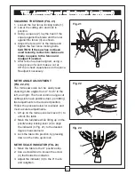
MITRE CUT (FIG. 30)
1. When a mitre cut is required, unlock the mitre table by releasing the mitre lock lever (1).
2. While holding the mitre handle (2), press down on the positive stop locking lever (3).
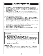
BEVEL CUT (FIG. 31)
1. When a bevel cut is required, loosen
the bevel lock handle (1) by turning it
clockwise.
2. Tilt the cutting head to the desired
angle, as shown on the bevel scale
(2).
3. The blade can be positioned at any
angle, from a 90° straight cut (0° on
the scale) to a 45° left/right bevel.
Tighten the lock handle (1) to lock the
cutting head in position. Positive bevel
stops are provided at 0° and 45°.
Fig. 31
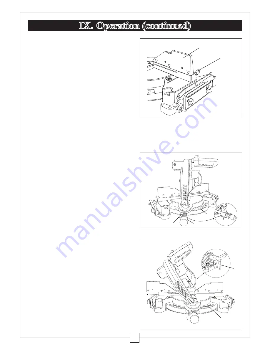
SLIDING FENCE (FIG. 29)
1. Unlock the fence cam locking knob
(1) by pushing it toward the rear of the
machine.
2. Extend the fence (2) by sliding it out
to match the degree of the bevel cut.
Lock the fence cam locking lever
by pushing it IN toward the fence.
NOTE:
When transporting the saw,
always secure the sliding fence in the
collapsed position (toward the saw
blade).
Fig. 29
!
1
2
1
3
4
1
2
2
Fig. 30
Summary of Contents for Maximum Hawkeye Laser 055-6746-0
Page 46: ...46 Notes ...
Page 47: ...47 Notes ...
Page 48: ...48 Notes Imported by Mastercraft Canada Toronto Canada M4S 2B8 ...


