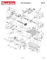
9
3. Clean out all chips or foreign
matter adhering to the cutter
block (8) and the blade.
4. Either turn over the planer blade
(7) or replace it if required.
5. Slide the good blade face up
into the blade retainer (17) of
the cutter block (8). The ridge
along the blade should be on the
opposite side from the clamping
screws (9).
NOTE:
The blades are preset so
that the cutting edge is level, i.e.,
parallel to the surface of the rear
shoe (11).
6. Tighten the clamping screws
(9), ensuring they are tightened
evenly.
7. Repeat for the second blade,
making sure that both blades
are set to the same cutting level
and positioned in the center of
cutter block (8). Otherwise your
planing surface will be rough and uneven. (Fig. 2-4)
NOTE:
Always change both blades at the same time, and use blades of the
same dimensions and weight, otherwise the resulting imbalance can cause
vibration, poor planing action and shorten the blade and tool life.
CAUTION:
Tighten all the clamping screws (9) carefully when attaching the
blades to the planer. A loose clamping screw could be extremely dangerous.
Regularly check to see they are
tightened securely.
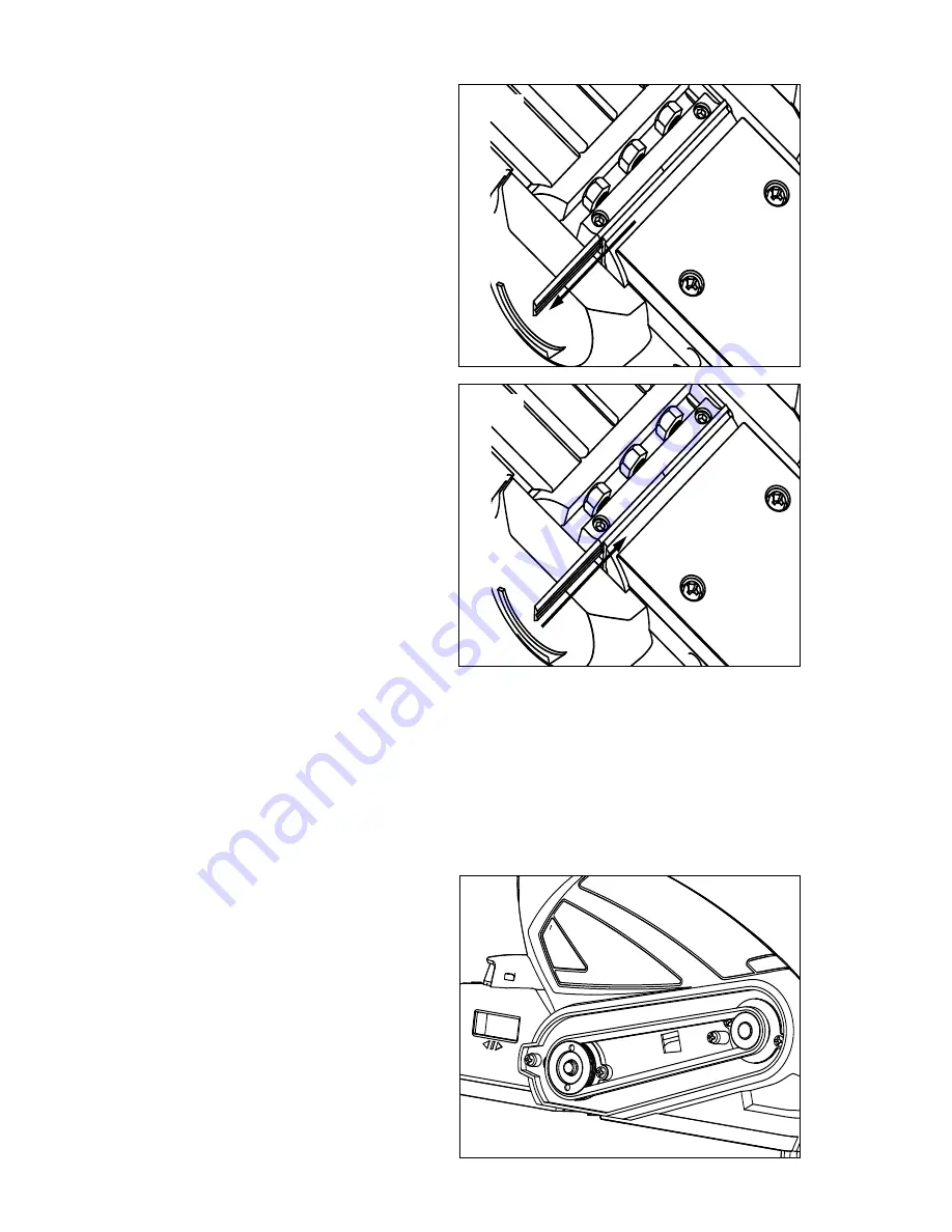
DRIVE BELT REPLACEMENT (Fig.5)
1. Remove the cross-head screws
that secure the drive belt cover
on the left-hand side of the
planer as viewed from the rear.
2. Remove the damaged belt and
use a soft brush to clean the
pulleys and the surrounding
area.
Fig. 3
Fig. 4
Fig. 5


