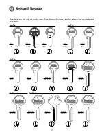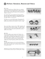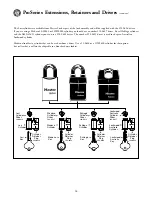
background image

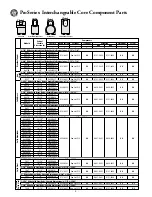
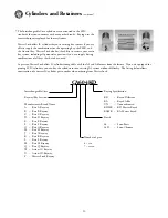
Master Lock keys are coded from bow to tip and with a few exceptions, the increment used
is .0155".  Master Lock keys will be encountered with two types of stamping on them.  
Both direct and blind codes are stamped on the keys for different products.  In the 291 pin
kit you will find the 290-0371 slip gauge for decoding keys.  For ProSeries

®

products, 

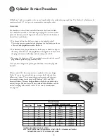
use the top slot in the gauge.  Insert the key in the slot at the large end perpendicular to 
the gauge.  Once inserted, pull the key toward the smaller end of the slot until it stops.  
The number stamped on the gauge directly below where the key stops is the cut depth for
that cut position on the key.  Repeat the process for each cut position on the key to
determine the actual combination of the key.

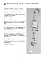
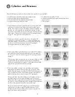
The cylinder being rekeyed may be set to an existing key combination or it may be zero-bitted.  In either case, follow the plug
out of the shell and discard the existing pins from the plug.  If the cylinder was Master Keyed, also remove any master pins that
may have been retained in the shell.  For the combination decoded, select the appropriate length pin from the 291 pinning kit,
and install in the appropriate pin chamber of the plug.  Once all pins have been installed, insert the plug into the shell and
check for smoothness of operation.  If you note roughness in the operation, check the key to be sure it has been produced to the
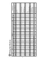
bitting specifications on page 20.

M

A S T E R

K

E Y I N G

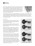
Most keying system software offers the option of providing a pinning
chart.  It is advisable to use that option.  If the option is not available, 
the following example illustrates the procedure required to determine 
the pinning of a master keyed cylinder.

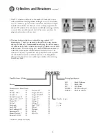
With the example master key combination of 047345 at right, and the
change key combination of 405253, the first step is to figure out the
bottom pins that you must install in the cylinder, then the required master
pins must be determined.

Bottom pins must be selected to allow operation of the shallowest cut 
per position in the cylinder for either key.  By comparing the two
combinations, select the shallowest cut for each cut position from either
key.  In our example we have highlighted the shallowest cut depth, 
and you can see that our bottom pins for the cylinder will be 005243.
The master pin sizes are determined by subtracting the shallowest cut
depth from the deepest cut depth for each pin position in the lock.  
As noted in the example, the difference is 442112.

From this process, we know that in the first pin chamber we must have 
a number zero bottom pin and a number 4 master pin for both keys 
to operate.  The illustration at the right shows the pinning for the master
keyed cylinder example.  Depending upon the size of your key system,
you may or may not require master pinning in all of the pin chambers.  

If you find that some cylinders require master pins in different pin
chambers or if different cylinders require different quantities of pin
chambers to have master pins, question the design of the system before
proceeding.  Having master pins in different pin chambers may indicate
that the system utilizes a Rotating Constant Method of progression, which
should be verified.  Having different quantities of master pins in different
cylinders usually indicates faulty key system design, and you should
recommend that the system be replaced.

Keying 

16

0

4 7 3

4

5

4

0 5 2

5

3

Bottom Pins are bold.

0 4 7 3 4 5

4 0 5 2 5 3

4 4 2 1 1 2

Difference equals master pins

Summary of Contents for ProSeries 6121

Page 1: ...T E C H N I C A L M A N U A L ProSeries Padlock ISSUE 4 01...

Page 2: ......

Page 3: ...integration into facility padlock and door lock systems Today ProSeries is the only product line available for so many different applications making Master Lock the source for complete commercial secu...

Page 4: ...ly If the lock only needs to be rekeyed it is not necessary to remove the extension ball bearings or shackle Two functions are available in the locks NKR Non Key Retaining and NRK Non Removable Key an...

Page 5: ...be reversed to reassemble the lock A light application of assembly grease may be used to hold the ball bearings in place during assembly If the lock only needs to be rekeyed it is not necessary to rem...

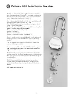
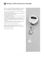
Page 6: ...inside the last pin chamber to allow 180 rotation of the plug Align pin chambers in plug with service holes in the bottom of the shell to remove existing bottom pins and replace with new combination R...

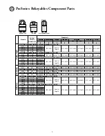
Page 7: ...3 4 293S6321 6121 0427 See List P 14 6121 0420 6121 0423 6121 0424 6121 0421 6121 0422 2 3 8 Wide Laminated Steel Body Shackle Dimensions a 3 8 c 7 8 6325 3 4 293S6325 6121 0427 See List P 14 6121 042...

Page 8: ...831 0421 6830 0422 6121 0421 6121 0422 7030LT 3 293LTS6830 Page 14 1 3 4 Wide Solid Steel Body Shackle Dimensions a 5 16 c 29 32 7040 1 3 16 293S6121 See List 7040LJ 2 1 2 293LJS6121 6121 0427 Page 14...

Page 9: ...plate extension ball bearings or shackle Two functions are available in the locks NKR Non Key Retaining and NRK Non Removable Key and both functions are accomplished as a design feature of the extensi...

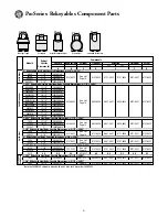
Page 10: ...421 6121 0424 N A N A 6841LJ 2 7 16 293LJS6121 6841BLJ 2 7 16 293LJB6840 2 Wide Solid Brass Body Shackle Dimensions a 3 8 c 29 32 6851 1 1 2 293S6125 6851B 1 1 2 293B6850 6121 0427 See List P 13 N A 6...

Page 11: ...in place during assembly If the lock only needs to be rekeyed it is not necessary to remove the extension ball bearings or shackle Two functions are available in the locks NKR Non Key Retaining and NR...

Page 12: ...1 3 4 Wide Solid Brass Body Shackle Dimensions a 5 16 c 29 32 6842 1 3 16 293S6121 6824B 1 3 16 293B6840 6842LF 1 1 2 293LFS6121 6121 0427 See List P 12 298 0629 6121 0423 6121 0424 N A 6621 0450 6842...

Page 13: ...mber 21 24 25 and 27 It may be rekeyed using our 291 pinning kit shown on page 19 There are times when you may want to use a four pin cylinder in a lock designed for the five pin cylinder because of k...

Page 14: ...a threaded hole used to mount it to the lock via the toe side shackle hole and the socket screw This cylinder also requires a special driver to be placed between the cylinder tail and the lock extensi...

Page 15: ...he factory If you are equipped for pinning SFIC cylinders you can key the cylinders into an existing A3 system without difficulty The listing below allows construction of a correct IC cylinder part nu...

Page 16: ...Once you have changed the pinning combination insert the plug into the shell Effective mid 2001 the crimp retainer is replaced with a new design E clip To service the new cylinder type remove the E c...

Page 17: ...to keyways and the corresponding part numbers Four Pin Five Pin Five Pin Five Pin Six Pin Keys and Keyways 15 900 K900 W900 S A F E T Y L O C K O U T K400 W400 K7000 W7000 K1 W1 K1R W1R K2 W2 K15 W15...

Page 18: ...determine the pinning of a master keyed cylinder With the example master key combination of 047345 at right and the change key combination of 405253 the first step is to figure out the bottom pins th...

Page 19: ...e taken to position them correctly within the lock during assembly Consult the component parts listings in this manual to determine the actual part numbers for the extensions RETAINERS There are three...

Page 20: ...r that can be used without a driver Use a 51 0600 or a 51W0600 cylinder for that option but realize that it will not be adaptable to a door hardware lockset ProSeries Extensions Retainers and Drivers...

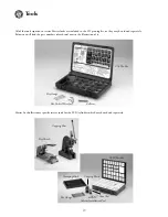
Page 21: ...nd the part numbers of each tool next to the illustration of it Master Lock offers some specific service tools for the SFIC cylinders which may be ordered separately Tools 19 291 Pin Kit Key Gauge Hex...

Page 22: ...355 0 2200 0 2045 0 1890 NA 0 187 0 125 50 81 82 1710 1714 81KM 0 283 0 2820 0 2665 0 2510 0 2355 0 2200 0 2045 0 1890 0 1735 0 187 0 125 81MK 82MK 1710MK 1714MK 81RES 0 283 0 2740 0 2585 0 2430 0 227...

Page 23: ...lock master key n the one pin master key for all combinations listed as a block in the standard progression format BMK abb block master key bolt n any movable projection which blocks the movement of o...

Page 24: ...le or removable core any chamber which has a control shear line which is different from the operating shear line control cut n any bitting which operates the retaining device of an interchangeable or...

Page 25: ...ck or cylinder fail safe adj a feature of a security device designed to release for safety purposes during a power loss fence n 1 a projection on a lock bolt which prevents movement of the bolt unless...

Page 26: ...cylinder is combinated to the top master key and a change key increment n a usually uniform increase or decrease in the successive depths of a key cut which must be matched by a corresponding change i...

Page 27: ...y must pass to enter a lock keying n any specification for how a cylinder or group of cylinders are or are to be combinated in order to control access keying conference n a meeting of the end user and...

Page 28: ...gned to lock utility meters or valves and which require either a key or special wrench for removal mis cut adj of or pertaining to a key which has been cut incorrectly n a mis cut key MK abb master ke...

Page 29: ...condition brought about when a key cut which is too high forces its tumbler into the locking position This type of locking does not rely on gravity or spring pressure post of a key n the portion of a...

Page 30: ...sing a shim shoulder n any key stop other than a tip stop see also bow stop shove knife n a tool used with a set up plug which pushes the springs and pin tumblers into the cylinder shell shrouded shac...

Page 31: ...ocess wherein key bittings are obtained by using the cut possibilities in two columns of the key bitting array two pin master key n a master key for all combinations obtained by progressing two bittin...

Reviews: