www.masterweld.co.uk
6.6 MIG Operation
Note:- Check that drive rolls, and torch parts are correct for the
wire size and type being used.
1. The optimum idle roll pressure varies with type of wire, wire
diameter, surface conditions, lubrication, and hardness. As a
general rule, hard wires may require greater pressure, and soft,
or aluminium wire, may require less pressure than the factory
setting. The optimum idle roll setting can be determined as
follows:
2. Press end of gun against a solid object that is electrically isolated
from the welder output and press the gun trigger for several
seconds.
3. If the wire “bird nests”, jams or breaks at the drive roll, the idle
roll pressure is too great. Back the adjustment knob out 1/2 turn,
run new wire. If the only result was drive roll slippage, loosen
the Hand nut on the central connector and pull the gun forward
about 6” (15cm) away from the power source. There should be a
slight waviness in the exposed wire. If there is not waviness, the
pressure is too low. Tighten the adjustment knob 1/4 turn, reinstall
the gun cable and repeat the above steps.
4.
When triggering, the electrode and drive mechanism are
electrically “LIVE” relative to work and ground and remain “LIVE”
several seconds after the gun trigger is release
d.
WARNING
When using an open arc process, it is necessary to use correct
eye, head, and body protection.
5. Position wire over joint. The end of the wire may be lightly
touching the work.
6. Lower welding helmet, operate gun trigger, and begin welding.
Hold the gun so the contact tip to work distance is about 3/8”
(10mm).
7. To stop welding, release the gun trigger and then pull the gun
away from the work after the arc goes out.
8. When no more welding is to be done, close valve on gas cylinder
(if used), momentarily operate gun trigger to release gas pressure
and turn off the machine.
NOTE:- These settings are guidelines only. Material and wire
type, joint design, fit up, position, shielding gas, etc. affect
settings. Produce test welds to be sure they comply
to specifications.
Welding circuit calibration.
The welding circuit resistance can vary, but the machine can be
set to compensate for this. Cut the welding wire flush with the front of
the contact tip and remove the outer nozzle. Select F60 from
the function menu while holding the contact tip firmly against the
work piece. Press the trigger three to five times for approximately 1
second to calibrate the circuit resistance. The correction figure will
be shown in the PH display (millivolts).
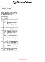
Material thickness determines weld parameters.
1. Convert Material Thickness to Amperage (A) (0.25mm= 1 Amp)
3.2mm = 125 A
2. Select Wire Size
Amperage Range
Wire Size
40 - 145 A
0.8 mm
50 - 180 A
1.0 mm
75 - 250 A
1.2 mm
3. Select Wire Speed (Amperage)
Wire Size
Feed speed
0.8 mm
0.05m/min per Amp
1.0 mm
0.04m/min per Amp
1.2 mm
0.025m/min per Amp
So based on 3.2 mm material thickness amperage should be 125A
if using 1.0mm wire then the wire feed speed should be
0.04 X 125= 5m/min
Wire speed (amperage) controls weld penetration
4. Select Voltage. Voltage controls height and width of weld bead
Low Voltage: wire stubs into work
High Voltage: arc is unstable (spatter)
Set voltage midway between high/low voltages.
And then fine tune accordingly
6.7 MMA Welding
Output Polarity Connections
Electrode polarity
MMA electrodes are generally connected to the ‘+’ terminal and the
work lead to the ‘-‘terminal
The twist connector on the wire feeder is a + outlet.
But if in doubt consult the electrode manufacturer’s literature.
MMA Welding Operation
WARNING
When using an open arc process, it is necessary to use correct
eye, head, and body protection.
MMA Welding Guide
Select JOB 7 and the left display will show the amperage and the
right display will show "EL". You can adjust the welding amperage
using the left-hand knob (4) you can alter the MMA Arc force, Hot
start, Arc Force. Using F70, F71, F72.
Effects of MMA welding various materials
High tensile and alloy steels
The two most prominent effects of welding these steels are the
formation of a hardened zone in the weld area, and, if suitable
precautions are not taken, the occurrence in this zone of under-bead
cracks. Hardened zone and under-bead cracks in the weld area may
be reduced by using the correct electrodes, preheating, using higher
current settings, using larger electrodes sizes, short runs for larger
electrode deposits or tempering in a furnace.
Manganese steels
The effect on manganese steel of slow cooling from high
temperatures is embrittlement. For this reason, it is absolutely
essential to keep manganese steel cool during welding by
quenching after each weld or skip welding to distribute the heat.
Cast iron
Most types of cast iron, except white iron, are weldable. White iron,
because of its extreme brittleness, generally cracks when attempts
are made to weld it. Trouble may also be experienced when welding
white-heart malleable, due to the porosity caused by gas held in this
type of iron.
13


