Fully tighten the metal band binding screw.
Replace, on the brake rod, the knurled adjusting nut, and adjust the rear brake.
(See Para. 90).
Allow time for the liquid jointing compound to set and then :—
Remove inspection cap from the chaincase and pour in engine oil to the level
mentioned in Para. 24.
Replace inspection cap.
Note :—
If, after replacing a front chaincase, it is found not to be oil tight the general
reason is distortion of the two joint faces. These faces must be undamaged and,
on test, should closely fit to a surface plate. They must also be absolutely clean
before replacement and the edges must be in exact register, one with the other.
Any distortion caused by accidental impact must be remedied before refitting.
If any doubt exists, check for distortion before assembly.
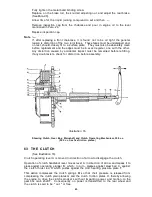
Illustration
16
Showing Clutch, Gear Box, Mainshaft and Clutch Operating Mechanism, 350 c.c.
(500 c.c. has five friction plates.)
63 THE CLUTCH
(See
Illustration
16).
Clutch operating lever A is moved in direction of arrow to disengage the clutch.
Operation of clutch handlebar lever moves lever A in direction of arrow and causes it to
press against operating plunger B, which, in turn, presses against steel ball C, against
the clutch thrust rod D which pushes against the clutch spring pressure plate F.
This action compresses the clutch springs M so that their pressure is released from
compressing the clutch plain plates G and the clutch friction plates H, thereby allowing
the engine to drive the clutch sprocket L without imparting power, and motion, to the
gear box main shaft T. Consequently no power is transmitted to the rear wheel and
the clutch is said to be " out " or free.
43
Summary of Contents for 46/G3L 1946
Page 2: ......
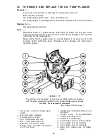
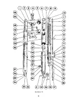
Page 54: ...Illustration 19 52 ...
Page 89: ...Illustration 36 Wiring Diagram Pictorial 87 ...
Page 91: ......
Page 92: ......

