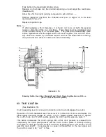
On allowing the clutch handlebar lever to return to its normal position the clutch
operating lever becomes " free " and the clutch spring pressure causes the clutch thrust
rod D, the steel ball C and the operating plunger B to move to the right.
The whole of the clutch spring pressure is thereby transferred to the clutch spring
pressure plate F and this forces the steel plates G tightly against the clutch friction
plates H to that power, transmitted by the engine to clutch sprocket L, is transferred
through clutch case J to friction plates H, to steel plates G, to clutch centre E which
causes the gear box main shaft T to revolve.
64 CLUTCH SPRING ADJUSTMENT
If clutch slip is experienced the most probable cause is incorrect cable adjustment.
If the clutch cable adjustment is found to be correct,
i.e.,
there is the clearance mentioned
in Para. 65, the clutch spring adjusting nuts should be adjusted.
To adjust clutch spring adjustment nuts :—
Obtain access to clutch spring adjustment nuts by removing outer half of front
chaincase. See Para. 61.
Screw home, one-half of a complete turn, each clutch spring adjustment nut.
Test machine for clutch slip.
If necessary, repeat, by screwing home a further half-turn but be careful to adjust
each of the nuts a similar amount.
If, to remedy clutch slip, it is necessary to screw nearly home the four nuts, this
is a clear indication that, either the clutch springs have lost their strength, and/or,
the fabric inserts in the clutch friction plates have worn so that they are past
further useful service. Replace with new.
The standard setting of the clutch spring adjusting nuts is obtained by fully tighten-
ing all four nuts and then unscrewing each exactly four complete turns.
65 CLUTCH ADJUSTMENT
Minor adjustment of the clutch operating mechanism is obtained by screwing,
in or out, the clutch cable adjuster located in the back of the kick-starter case.
Major adjustment of the clutch operating mechanism is o b t a i n e d by altering the
position of the fulcrum pin of the clutch operating lever in the kick-starter case.
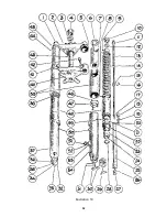
(Lever A in Illustration 16 and 175-X-4 in Illustration 17).
This Major adjustment is explained below. (See Illustration 17)
175-X-4 is the gear box clutch operating lever, and 66-X-7 is the pin on which
it hinges.
329-X is the operating lever fork and this, slides in the kick-starter case cover.
Its position being determined by the sleeve nut 331-X.
Cap 328-X is secured to the outside of the kick-starter case cover, being fixed
by the two screws 333-X and acts as a locking device for the sleeve nut 331-X
and acts as a locking device for the sleeve nut 331-X.
It is essential that there is about 1/32" clearance between the operating plunger
330-X and the nose on operating lever 175-X-4 when the clutch is in the engaged,
or driving position.
It will be appreciated that, as the result of wear on the fabric inserts in the clutch
friction plates, the plates will tend to close up towards each other. This increases
the effective length of the clutch thrust rod. On the other hand, the clutch
control inner wire tends to stretch in use. These two actions will neutralise
each other but the fact remains that, from time to time, it is necessary to adjust
the rod clearance and also take up cable stretch.
Clutch slip caused by the clutch thrust rod permanently bearing on the spring
pressure plate will rapidly ruin the fabric inserts and thrust rod. In addition,
the heat generated by this may be so intense that the hardening of the clutch
springs and the two ends of the thrust rod may be adversely affected.
Therefore, the importance of correct adjustment, and inspection of same to see
the adjustment is maintained, must be stressed.
44
Summary of Contents for 46/G3L 1946
Page 2: ......
Page 54: ...Illustration 19 52 ...
Page 89: ...Illustration 36 Wiring Diagram Pictorial 87 ...
Page 91: ......
Page 92: ......

