Re-fit in the reverse order but, before finally tightening the rear wheel spindle nuts,
ensure the speedometer gear box is so positioned that the speedometer driving cable
can be correctly replaced.
When the wheel alignment is correct a piece of thin string stretched taut across both
wheels, about four inches from, and parallel to, the ground, should just touch each tyre
at both sides of the wheel centres.
Alternatively, a straight wooden batten, about five feet long, is handy to use for checking
wheel alignment. This should be applied, as in the case of string, parallel to and about
four inches from the ground.
Note :—
Always check the rear chain tension and the rear brake adjustment after making
an alteration to the rear wheel position. (See Paras, 68 and 90).
83 WHEEL BEARINGS AND ADJUSTMENT
The wheel bearings are of taper roller type. The inner bearings for the rollers are
Integral with the wheel spindle. The outer cups for the rollers are pressed into the
hub shell. They have a fixed location on one side and an adjustable location on the other.
On the outer side of each taper roller bearing is an oil sealing ring.
Adjustment is obtained by a ring screwed into the hub shell and which abuts against the
moveable bearing cup. This adjusting ring is locked in position by a large circular lock
ring, or nut.
On the rear wheel the adjustment is made on the left-hand, or brake, side, but, on the
front wheel, it is on the right-hand side.
It is rarely necessary to make adjustment to wheel bearings. It is most important
they are not adjusted too tightly as this would quickly ruin them. There must always
be a slight amount of end play, This should be about .002".
To adjust the rear wheel bearings the wheel must bo removed from the machine, but
those of the front wheel can be dealt with in situ.
A service method of ensuring correct adjustment is to :—
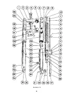
First slacken the lock nut (16 in Illustration 21).
Then tighten the adjusting ring (17 in illustration 21) until all slackness has been
taken up and then to slacken it back exactly one-half turn.
Finally, tighten the lock ring (16), making sure that, when doing so, the adjusting
ring (17) does not creep round.
84 TO DISMANTLE A WHEEL BEARING
Prepare :—
Remove the wheel from the machine. (See Paras. 81 or 82).
Remove :—
Brake cover plate with brake shoes, etc., (If rear wheel also withdraw centre
solid spindle and remove the speedometer drive gear box).
Slacken :—
Lock ring. (16 in illustration 21). (Use spanner 11914-S).
Unscrew :—
Adjusting ring. (17 illustration 21).
60
Summary of Contents for 46/G3L 1946
Page 2: ......
Page 54: ...Illustration 19 52 ...
Page 89: ...Illustration 36 Wiring Diagram Pictorial 87 ...
Page 91: ......
Page 92: ......


