background image

Illustration

  22

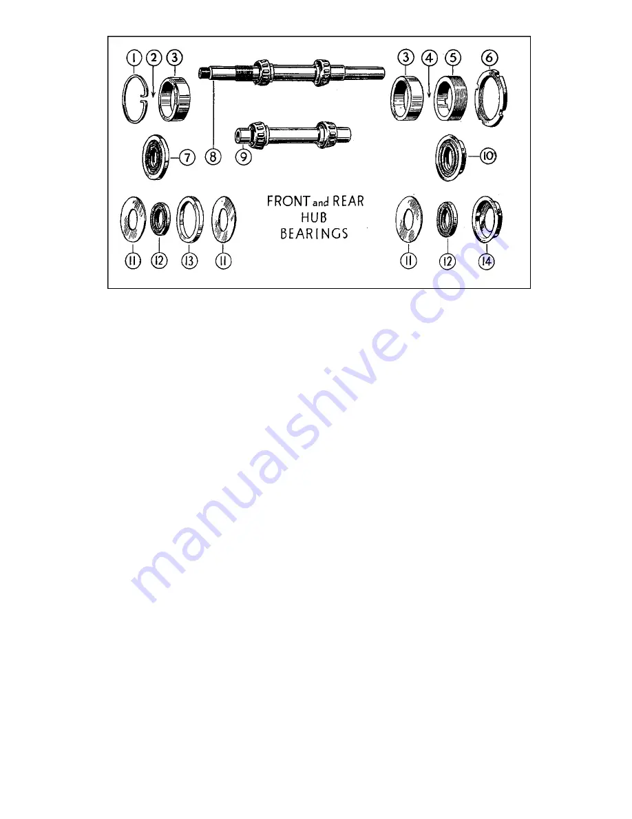
Showing  exploded  view  of  hub  bearing  components.

1

2

3

4

5

6

7

SPRING  CIRCLIP,  (FITS  IN  GROOVE  CUT

IN  UNTHREADED  END  OF  HUB.

OIL  SEAL  ASSEMBLY,  CONSISTING  OF  : 

1  SPACING  RING  (11)
1  OIL  SEAL 

(12)

1  COLLAR 

(13)

1   SPACING  RING  (11)

FITS  HERE,  BETWEEN  THE  BEARING  CUP

(3)  AND  THE  SPRING  CIRCLIP  (1).

OUTER CUP OF TAPER ROLLER BEARING. 

(*).

OIL  SEAL  ASSEMBLY,  CONSISTING  OF  : 

1  SPACING  RING  (11)
1   OIL  SEAL 

(12)

1  DISHED  CUP   (14)

FITS  HERE,  BETWEEN  THE  BEARING  CUP

(3)  AND  THE  BEARING  ADJUSTING

RING  (5).

ADJUSTING  RING,  FOR  BEARINGS.

LOCK  NUT,  FOR  BEARING  ADJUSTING

RING.

AN  OIL  SEAL  (12)  ENCIRCLED  WITH  ITS

SPACING  COLLAR  (13).

8

9

10

11

12

13

14

*

FRONT  WHEEL  SPINDLE,  WITH  SET  OF

TAPER  ROLLERS  MOUNTED  IN  TWO

CAGES.

REAR  WHEEL  HOLLOW  SPINDLE  WITH

SET  OF  TAPER  ROLLERS  MOUNTED  IN

TWO  CAGES.

AN OIL  SEAL (12) SHOWN  PRESSED  INTO

A  DISHED  CUP  (14).

RETAINING SPACING  RING,  OR WASHER,

FOR  OIL  SEAL.

OIL  SEAL.

SPACING  COLLAR,  (THIS  ENCIRCLES

THE  OIL  SEAL  FITTED  TO  THE  UN-

THREADED  END  OF  A  HUB.)

DISHED  CUP,  (THIS  CONTAINS THE OIL

SEAL FITTED  TO  THE  THREADED  END OF

A  HUB.

These  are  not  supplied  separately.  A 

front,  or  rear  wheel  spindle  complete

with  taper  roller  bearings  includes  two

of  these  bearing cups.

Also  rollers  are  not  supplied  separately.

61

Summary of Contents for 46/G3L 1946

Page 1: ...TOR CYCLES PROPRIETORS ASSOCIATED MOTOR CYCLES LIMITED P LU M S T E AD LO N D O N S E 18 MAINTENANCE MANUAL AND INSTRUCTION BOOK for 1 9 4 6 350 c c and 500 c c CLUBMAN MODELS O H V MA TCHLESS EDITION CM 1 Revised ...

Page 2: ......

Page 3: ... MATCHLESS MOTOR CYCLES Proprietors ASSOCIATED MOTOR CYCLES LIMITED Registered Offices PLUMSTEAD ROAD PLUMSTEAD LONDON S E 18 ENGLAND Nearest Station WOOLWICH ARSENAL Southern Railway Factories BURRAGE GROVE and MAXEY ROAD PLUMSTEAD S E 18 Telegrams and Cables MATCHLESS WOL LONDON Telephone WOOIwich 1 22 3 5 Lines Codes A B C 5th and 6th Edition Bentley s and Private Codes All correspondence to MA...

Page 4: ...In consequence it must be intelligently and efficiently maintained in order to provide unfailing reliability In this book are non technical instructions for carrying out all the maintenance operations likely to be called for in strenuous service and Illustrations are provided to assist Neglect to make essential adjustments only casual attention to lubrication and the lack of periodical maintenance...

Page 5: ...tted b Capacities Front fork Gear box Oil tank Petrol tank 6 fluid ounces 1 lb 14 ozs 3 pints 3 gallons c Carburetter Main Jet size Throttle size Choke size Taper needle 350 500 350 500 350 500 350 500 150 180 6 4 29 4 1 inch diameter 1 3 32 inches diameter T 6 Std T 29 Std Taper needle located in 3rd notch from top 350 and 2nd from top 500 d Chains Front chain Rear chain Dynamo chain Magneto chai...

Page 6: ...ead centre h Sparking plug Type Thread Reach Point gap CHAMPION L 10 on 350 c c LODGE H 145 on 500 c c 14 Millimetres 020 to 025 i Piston dimensions Top land Second land Third land Top of skirt Bottom of skirt 350 2 6877 2 6962 2 6962 2 7132 2 7143 500 3 2145 3 2260 3 2190 3 2435 3 2446 All above measurements are subject to a toleration limit of or 0005 j Piston rings Model 350 500 Diameter 2 23 3...

Page 7: ...19 32 1 687 Exhaust head diameter 1 1 687 Stem diameter a a Seat angle 45 45 Valve head measurements are subject to a toleration limit of or 0005 Valve stem actual measurement is minus 0035 to minus 0045 n Valve springs 350 and 500 2 g n i r p s e v l a v r e t u O f o h t g n e l e e r F z Free length of Inner valve spring 1 m Renew valve springs when free length is more than x e v o b a e h t w ...

Page 8: ...ing use in conjunction with rear brake appli cation See Para 9 Rear brake pedal Depress with left foot to apply rear brake Apply gently and use increasing pressure as road speed decreases Gear change pedal Controls selection of the four speeds or ratios between engine and rear wheel revolutions with a free or neutral position See Para 7 and Illustration 3 Kick starter pedal The almost vertical ped...

Page 9: ...ly ones that may require alteration to suit the individual taste of the rider are the foot brake pedal see Para 89 and the gear change foot pedal see Para 7 If any adjustment is made to the rear brake pedal make certain the brake does not bind and also see there is not excessive free pedal movement before the brake comes on See Para 90 Illustration 1 Showing controls The dip switch reference 17 it...

Page 10: ...petrol plus the free use of the gear box to prevent the engine labouring under heavy stresses at low engine speeds Two petrol taps are situated underneath the rear end of the petrol tank One each side Both must be shut off when the machine is left standing for more than a few minutes The tap plungers work horizontally To open the hexagon knob marked Push On is pushed towards the body of the tap To...

Page 11: ... kick with the valve closed and the engine should immediately fire The kick starter mechanism must be allowed to properly engage before putting heavy pressure on the kick starter crank pedal pin That means there are two definite and separate movements when operating the mechanism by depressing the crank The first is a Mow and gentle movement which ends when it is felt the quadrant has engaged with...

Page 12: ... and leave it in that position unless it is necessry to retard in order to ease the engine and so prevent pinking when pulling hard on a gradient 8 NOTES ON DRIVING If at first the lowest gear will not engage release the clutch lever and after a second or two make another attempt This condition may exist in a new machine but it tends to disappear after a little use Always endeavour to make the mov...

Page 13: ...nsequent risk of engine seizure When using the machine on wet or greasy roads it is generally better to apply BOTH brakes together because sudden or harsh application of either brake only under such conditions may result in a skid In all conditions it is advisable to make a habit of always using both brakes together rather than to habitually using the rear brake and reserving the front brake for e...

Page 14: ...at until this surplus is cleared the return flow is very positive and continuous Therefore If the oil circulation is deranged the fact is apparent at once by the lack of a steady return flow It should be remembered that normally the return flow is somewhat spasmodic and mixed with air bubbles This is partly due to the fact that the return portion of the oil pump plunger has greater pumping capacit...

Page 15: ... FRONT FORKS FOR REAR CHAINS Castrol Grand Prix Triple Shell Mobiloil D Essolube Racer Motorine B de Luxe As S A E 50 Castrol X X L Double Shell Mobiloil B B Essolube Racer Motorine C As S A E 30 Castrolease Medium Shell Retinax Grease Mobilgrease No 2 Esso Grease Belmoline C Castrolite Single Shell Mobiloil Arctic Essolube 20 Motorine E As S A E 20 Tallow When buying oils and greases it is advisa...

Page 16: ...he cork piston The gun may be filled by inserting the grease in the barrel of the gun by means of a lath or similar spoon However it is better to obtain the grease packed in the special containers that are supplied having loose collars in which are holes so that by placing the barrel of the gun over the hole in the central floating plate and pressing downwards the gun is instantly charged with gre...

Page 17: ...hrough timing side flywheel axle timing side flywheel and crank pin to lubricate big end bearing The splash passes to interior of cylinder to lubricate cylinder and piston and then falls into crankcase sump b Passage in crankcase controlled by ball valve direct to cylinder to assist in cylinder and piston lubrication and then falls into crankcase sump c Passage in timing gear case where it builds ...

Page 18: ...tions No adjustment is provided except for the oil feed to the inlet valve stem This adjustment is made by a needle pointed screw located in the right side of cylinder head See Illustration 6 It is locked in position by a nut The approximate correct setting is half a complete turn from the fully closed position Once set it requires little or no adjustment Inlet valve squeak indicates the oil feed ...

Page 19: ...PPED HOLE TO ACCOMMODATE CARBURETTER RETAINING STUD PLAIN HOLE TO ACCOMMODATE CYLIN DER HEAD RETAINING BOLT INLET PORT TAPPED HOLE TO ACCOMMODATE CARBURETTER RETAINING STUD 10 11 12 13 14 15 16 TAPPED HOLE TO ACCOMMODATE NEEDLE SCREW NEEDLE SCREW ADJUSTING OIL FEED TO INLET VALVE GUIDE LOCK NUT FOR NEEDLE ADIUS71NG SCREW PLAIN HOLE FOR OIL FEED TO EXHAUST VALVE GUIDE PLAIN HOLE FOR OIL FEED TO INL...

Page 20: ...asher and then fully tighten knurled screw Essential this is kept tight otherwise cap assembly will be lost Rear driving chain should be removed for lubrlcaiion Clean chain in paraffin drain and wipe Immerse in bath of molten tallow leave for several minutes remove and allow excess lubricant to drain off and then replace on machine Engine oil is a poor substitute for tallow and if used chain shoul...

Page 21: ...crew the two hexagonal plugs at top of fork inner tubes These are on level with handlebars Pull upwards each plug at far as possible Attached to undersides of plugs are the fork damper rods Rods will therefore be exposed Work plugs and rods up and down several times pumping action making upward strokes as violent as possible but only use fingers to do so This action is to eject any hydraulic fluid...

Page 22: ... smear some round the friction spring and on the drum in which the inner control wire is wound Then replace the grip and screws and fully tighten same 34 LUBRICATION CHART Illustration 7 Lubrication Chart Engine oil Locations Grease Locations Hydraulic Fluid Location Tallow Location 2 3 10 11 12 13 16 17 Front hub Rear hub Magneto chain case Steering head bearings Gear box Speedometer gear box Fro...

Page 23: ...nd re fill if necessary Tyres Check pressures and inflate if necessary See Para 97 WEEKLY Battery Inspect each cell for level of electrolyte and top up if necessary See Para 100 Brakes Inspect front and rear brake adjustments and alter if necessary See Paras 90 and 91 MONTHLY Tappets Check adjustment and alter if necessary See Para 50 Steering head Test for up and down play and adjust if necessary...

Page 24: ...a 83 Stands Smear hinge bolts with engine oil Contact points Clean and if necessary re set gap See Para 99 Contact tappet Clean and smear with thin oil See Para 99 Carburetter Remove float chamber and clean interior Magneto and Dynamo Get a Lucas Service Station to dismantle clean service and lubricate Front chaincase Remove inspection cap and check oil level 19 Top up if necessary Level not to be...

Page 25: ...uantity EVERY 2 000 MILES Oil tank Drain and re fill with new oil Oil should be changed after first 500 and 1 000 miles running Tank drain plug is on front lower edge of tank and crankcase sump drain plug is in bottom of crankcase on right hand side Have machine on front and rear stands or with both wheels on the ground when draining Clean felt oil filter and metal strainer each time the engine oi...

Page 26: ...s this operation by removing the need to first drain the tank of petrol 37 TO REMOVE THE PETROL TANK Disconnect the petrol feed pipe from both petrol taps Have taps in OFF position Cut the wires locking the four tank fixing bolts Unscrew the tank fixing bolts and tank may be removed from the frame Illustration 8 Showing details and order of assembly of the fuel tank fixing bolts and components 24 ...

Page 27: ...emove the seven bolts retaining rocker box to cylinder head Tilt upwards the right hand side of rocker box and extract the two Iong push rods Lay these aside so they may be identified because although identical in design they should not be interchanged Raise forward end of rocker box to clear the exhaust valve assembly swing it round in an anti clockwise direction to clear the frame tube and then ...

Page 28: ...he three fibre washers and three retaining nuts Beware of over tightening the three nuts Replace petrol tank See Para 38 41 TO REMOVE THE CYLINDER HEAD Remove The petrol tank See Para 37 The sparking plug The Rocker box See Para 39 Remove the right hand side footrest by Remove nut and washer on right hand side of footrest rod Partially withdraw footrest rod from left hand side Prise away the right...

Page 29: ...ed for re fitting In case of doubt see marking In or Ex on top of stem above collet grooves Need for decarbonisation depends on fuel oil and driving conditions It will be indicated by a tendency to knock on hills or accelerating after rounding a corner Every two thousand miles is a fair average Generally only necessary to take off cylinder head clean head and piston top of deposit and grind in val...

Page 30: ...at Finally remove all traces of grinding compound from the valves and seatings by washing off with petrol and pass a piece of clean rag through each valve guide to remove any abrasive that may have collected Ensure both valve ports are free from carbon deposit If a valve seat is re cut the cutting tool should have an angle of 45 When grinding in valves a suitable valve holding tool is necessary Th...

Page 31: ...er barrel Place a rubber gland round each tappet guide Place the cylinder head in position Ensure each cylinder head securing bolt has a plain steel washer on it and then replace the bolts and engage each a few turns Finally screw down the cylinder head securing bolts In turn bit by bit till all are fully home Replace The rocker box See Para 40 The carburetter The exhaust system The footrests The ...

Page 32: ... jointing compound and apply it to cylinder base Ensure jointing does not choke any of the cylinder base oil holds Smear cylinder bore and piston with engine oil Space piston rings so that the gaps are evenly spaced at 120 to each other Remove rag from crankcase throat Fit barrel over piston Ensure each piston ring is fully compressed into its groove in turn as the barrel passes over it Replace cy...

Page 33: ...ion D in Illustration 10 is in line with the centre of the inlet rear camshaft bush Insert the inlet camshaft so that the mark on it is in mesh with the mark on the small timing pinion D Rotate the engine in a forward direction till the mark on the small timing pinion D in Illustration 11 is in line with the centre of the exhaust front camshaft bush Insert the exhaust camshaft so that the mark on ...

Page 34: ...ary Note The part marked C in Illustration 12 is the top end of the long push rod It is threaded and the adjusting screw A screws into it In normal conditions tappet adjustment should not be necessary more frequently than about every five thousand miles or after decarbonising and grinding valves If adjustment is found necessary more frequently the cause should be investigated at once In no circums...

Page 35: ...by partially rotating engine forwards or backwards it is felt the piston is at the top of its stroke Mark rod flush with top face of sparking plug hole Remove rod and measure v above the flush mark and record position on rod Plate handlebar ignition control lever in fully advanced position Replace rod in sparking plug hole Slightly rotate engine BACKWARDS until upper mark on rod is flush with top ...

Page 36: ...ore tightening down otherwise serious damage will result when revolving engine Illustration 13 The rotating oil pump plunger is here shown partially withdrawn together with the guide screw which registers in the plunger profiled groove thereby providing the reciprocating movement By courtesy of Motor Cycling 1 2 3 4 5 6 7 DOWEL PEG LOCATING TIMING GEAR COVER BUSH FOR INLET CAMSHAFT PLUNGER FOR OIL...

Page 37: ... Spare Parts Department does not stock every part of the Carburettor but confines its stock to those parts that from time to time may need replacement as the result of wear Those parts include float chamber floats and needles jet taper needles needle jets and washers For all other parts application should be made through the local dealer to the manufacturers 55 CARBURETTER FUNCTION The petrol leve...

Page 38: ... not unduly sensitive and it should be possible to obtain the correct adjustment in a few seconds In the event of adjustment of the air screw failing to provide the required result it is possible the pilot jet is obstructed with dirt The pilot jet is actually a passage drilled in the sprayer base or choke and is very small to there is always latent danger of this becoming choked See Para 55 Upon r...

Page 39: ...Illustration 14 Showing details of the pilot jet with its air adjusting screw and the throttle stop screw F M 37 ...

Page 40: ... Test compression with throttle wide open 58 TWIST GRIP ADJUSTMENT A screw is provided in one half of the twist grip body to regulate the spring tension on the twist grip rotating sleeve This screw is locked by a nut and it must be screwed into the body to increase the tension The most desirable state of adjustment is that when the grip is quite free and easy to turn but at the same time will stay...

Page 41: ...movement is controlled by a bolt that has an eye encircling the gear box top fixing bolt and which passes through an eye block secured to the right hand side engine rear plate Illustration 15 The Transmission of power or drive through the gears may easlly be traced on above illustration 60 TRANSMISSION OF POWER THROUGH GEARS See lllustration 15 First or lowest gear Sliding gear C on mainshaft is i...

Page 42: ...l sprocket by the rear driving chain 61 TO REMOVE FRONT CHAINCASE AND CLUTCH To remove outer half of front chaincase Place tray under engine to catch oil Disconnect brake rod at pedal end Remove battery from its carrier Remove screw binding chaincase metal band at its rear Remove metal band Slightly prise up battery carrier if necessary Remove rubber band Remove nut and washer in centre of chainca...

Page 43: ... tighten the three bolts and turn up the tabs of the three lock washers Fit spacer inside chaincase d long to the centre fixing bolt Fit nut to centre fixing bolt and fully tighten Fully tighten long headed bolt holding rear chain guard to front chaincase Fit dynamo sprocket and chain and engine shock absorber by Ensure dynamo sprocket key is in position in dynamo armature shaft Ensure the spacing...

Page 44: ...0 c c six plain and five friction on 500 c c Drop into the spring pressure plate the four clutch spring cups Show up the spring pressure plate and insert over the studs the four clutch springs retaining each one a few turns as fitted with a clutch spring adjusting nut Fully tighten the four clutch spring adjusting nuts Slacken back four complete turns each clutch spring adjusting nut An old and br...

Page 45: ...ny doubt exists check for distortion before assembly Illustration 16 Showing Clutch Gear Box Mainshaft and Clutch Operating Mechanism 350 c c 500 c c has five friction plates 63 THE CLUTCH See Illustration 16 Clutch operating lever A is moved in direction of arrow to disengage the clutch Operation of clutch handlebar lever moves lever A in direction of arrow and causes it to press against operatin...

Page 46: ...stment of the clutch operating mechanism is obtained by screwing in or out the clutch cable adjuster located in the back of the kick starter case Major adjustment of the clutch operating mechanism is o b t a i n e d by altering the position of the fulcrum pin of the clutch operating lever in the kick starter case Lever A in Illustration 16 and 175 X 4 in Illustration 17 This Major adjustment is ex...

Page 47: ...djustment of the clutch operating mechanism is obtained by Slacken nut on the cable adjuster screwed into the back of the kick starter case To decrease the effective length of the clutch control cable i e to take up play between the control and the clutch thrust rod unscrew the cable adjuster from the kick starter case A few turns should be ample To provide a greater amount of play screw into the ...

Page 48: ...rear nut on adjusting eye bolt until with the finger through the inspection cap orifice it can lie felt that the chain is dead tight Then slack off the rear out and carefully tighten the forward nut until the correct chain tension is obtained after which securely tighten the rear nut to lock Correct chain whip a inch Check adjustment in more than one position and adjust as above at tightest place ...

Page 49: ...o dynamo driving sprockets can be varied thereby allowing lattitude for chain adjustment Tighten dynamo chain by Remove inspection cap from front chaincase See Para 34 Slacken dynamo clamping strap bolt Apply spanner RTK 1 to the flats cast on the dynamo end plate left hand side of dynamo and rotate dynamo in an anti clockwise direction till by passing a finger through the inspection cap opening i...

Page 50: ...el of the engine oil in the front chaincase is maintained according to the instructions given in Para 24 The shock absorber spring is retained by a cap washer and a sleeve lock nut The sleeve nut must be fully tightened against the shoulder of the driving side flywheel axle The dynamo sprocket is integral with the engine sprocket Behind the engine sprocket is a spacing collar which is a sliding fi...

Page 51: ...e fingers over the gap between handlebar lug and top frame lug at the same time exerting upward pressure by lifting from the front edge of front mudguard Continue to tighten the lower adjusting nut until no perceptible movement can be felt and yet the steering head is perfectly free to turn then tighten down the domed nut to lock the adjustment Tighten the two fork crown bolts Remove packing from ...

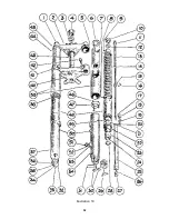
Page 52: ...upward through the holes A in the bottom ends of the damper tubes and also through holes B in the bottom ends of the main inner tubes See illustration 18 At the same time oil pressure lifts the damper valve and fills the tube between this valve and the plunger sleeve This displacement of oil upon impact imposes a certain amount of damper effect the extent of which increases with the violence of th...

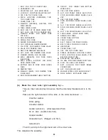
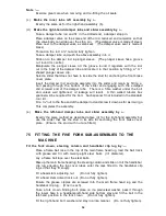
Page 53: ...semblies a Fork crown and cover tube assembly b Inner tube right assembly c Inner tube left assembly d Right hand damper tube and slider assembly e Left hand damper tube and slider assembly a Make the fork crown and cover tube assembly by Fit steering column into fork crown and secure lower end with circlip Force column upwards as far as it will go in fork crown so that circlip lies in fork crown ...

Page 54: ...Illustration 19 52 ...

Page 55: ... BUSH CAP FOR FORK SLIDER NUT FOR FRONT WHEEL AXLE STUD STUD SECURING FRONT WHEEL AXLE CAP CAP FOR FORK SLIDER STUD SECURING FRONT WHEEL AXLE CAP NUT FOR FRONT WHEEL AXLE STUD STUD SECURING FRONT WHEEL AXLE CAP N U T FOR FRONT WHEEL AXLE S T UD FORK SLIDER RlGHT HAND SIDE SPRING FOR FORK COVER TUBE BOTTOM FORK CROWN BOLT PINCH FOR FORK CROWN BOLT PINCH FOR FORK CROWN HEAD STEM COVER TUBE TOP CAP F...

Page 56: ... walled tubular box spanner will be required for the bolt Such spanner ft not Included in the standard tool kit Fit a c nut to the free end of the damper rod and screw it down as far as it will go This completes the assembly e Make the left hand damper tube and slider assembly by Exactly the same method as described above d for the right hand assembly but use the slider that has the stud in its si...

Page 57: ...lug sufficiently for the flexible wire to be detached Take a domed top bolt and place on it a large plain steel washer Screw the domed bolt on to the damper rod and then lock it in position by unscrewing the c nut on the damper rod till it tightly abuts against the under side of the domed bolt Make sure the c nut is tightly locked against the bolt and do not screw the domed bolt into the end of th...

Page 58: ...l Test fork for freedom of action and if any stiffness is felt loosen the nuts on the right hand side spindle clamp and work fork up and down Then tighten spindle clamp nuts Adjust steering head See Para 72 Fully tighten the two fork crown binding bolts These pass through the lower ends of the head lamp bottom stays Note During assembly absolute cleanliness is essential because any dirt or other a...

Page 59: ...n it two spacers and one washer Remove the two nuts retaining oil tank and battery carrier to the two frame studs and washer under each nut Oil tank and battery carrier are now free to be taken away and when doing so it is necessary to give each a slight rotary movement in order to disengage from the frame studs Note The frame studs are brazed to the frame To re fit Locate tank and battery carrier...

Page 60: ...structions given in Para 75 Do not attempt to use the FRONT STAND unless the machine is already supported by the REAR STAND 82 TO REMOVE REAR WHEEL Prepare Place machine on rear stand Disconnect Rear lamp wire at connection near rear wheel spindle Speedometer driving cable Unscrew gland nut on cable Rear chain connecting link Allow chain to hang clear of the rear wheel sprocket without becoming di...

Page 61: ... NUT NUT SPROCKET BOLT BRAKE LINING BRAKE COVER PLATE LOCK NUT BEARING ADJUSTING RING RING ADJUSTING BEARING BRAKE SHOE 19 20 21 22 23 24 25 26 27 28 29 30 31 32 33 34 DISHED CUP FOR OIL SEAL FORK END OF FRAME WASHER SOLID SPINDLE NUT SOLID SPINDLE SPACER BETWEEN BRAKE COVER PLATE AND FORK END FLAT PART FITS IN FORK END SLOT SPACER INSIDE BRAKE COVER PLATE SPROCKET AND BRAKE DRUM HUB FLANGE LEFT S...

Page 62: ...ed by a ring screwed into the hub shell and which abuts against the moveable bearing cup This adjusting ring is locked in position by a large circular lock ring or nut On the rear wheel the adjustment is made on the left hand or brake side but on the front wheel it is on the right hand side It is rarely necessary to make adjustment to wheel bearings It is most important they are not adjusted too t...

Page 63: ...BEARINGS LOCK NUT FOR BEARING ADJUSTING RING AN OIL SEAL 12 ENCIRCLED WITH ITS SPACING COLLAR 13 8 9 10 11 12 13 14 FRONT WHEEL SPINDLE WITH SET OF TAPER ROLLERS MOUNTED IN TWO CAGES REAR WHEEL HOLLOW SPINDLE WITH SET OF TAPER ROLLERS MOUNTED IN TWO CAGES AN OIL SEAL 12 SHOWN PRESSED INTO A DISHED CUP 14 RETAINING SPACING RING OR WASHER FOR OIL SEAL OIL SEAL SPACING COLLAR THIS ENCIRCLES THE OIL S...

Page 64: ...in the hub Take a plain washer and insert it in the unthreaded end of the hub shell Take an oil seal and press it into the collar 13 illustration 22 and then place this assembly so that it lies against the washer mentioned in the preceding paragraph Place a plain washer against the oil seal assembly Insert the spring ring in the groove cut in the unthreaded end of the hub shell making sure it lies...

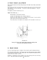
Page 65: ...able thrust collar See Para 87 87 BRAKE SHOE ADJUSTMENT Brake adjustment to compensate for lining wear is normally made by means of a finger adjuster on the rear brake rod and a cable adjuster for the front brake cable After a very considerable mileage this continual adjustment causes the brake expander to occupy a position whereby the available leverage is considerably reduced and consequently th...

Page 66: ...E OF THE TWO DEEP SLOTS OF THE THRUST COLLAR USED WHEN BRAKE LININGS ARE NEW THE BRAKE EXPANDER THRUST COLLAR ONE OF THE TWO MEDIUM DEPTH SLOTS OF THE THRUST COLLAR USED WHEN BRAKE LININGS HAVE HAD REASONABLE WEAR HOLE TO ACCOMMODATE THE BRAKE SHOE SPRING BRAKE SHOE HEEL WHICH PIVOTS ON THE PIN FORMING AN INTEGRAL PART OF THE BRAKE COVER PLATE 88 FRONT BRAKE COVER PLATE It is essential the front b...

Page 67: ...nor adjustment of the rear brake shoes is made by altering the position on the rear brake rod of the knurled adjusting nut Screw further on the rod to take up the brake Adjust rear brake by Place machine on rear stand Screw further on the rear brake rod the knurled adjusting nut till by rotating the rear wheel it can be felt the brake shoes are just touching the brake drum Then unscrew the adjusti...

Page 68: ...e front wheel it can be felt the brake shoes are just touching the brake drum Then screw down the adjuster two complete turns and tighten the lock nut Illustration 26 Showing front brake cable adjuster thread exhausted indicating brake shoe thrust collar adjustment is essential 92 BRAKE DRUMS The front wheel brake drum is retained to the wheel by eight countersunk screws The rear wheel brake drum ...

Page 69: ...oil gets on the tyres or spokes clean it off with petrol 95 TYRE REMOVAL It it not essential to remove a wheel from the machine to repair a puncture but it will usually be found desirable and more convenient to do so Take off outer cover and remove inner tube by Remove Cap from tyre valve Nut from tyre valve Inside from tyre valve This allows inner tube to deflate Most valve caps have a slotted to...

Page 70: ...e the tyre spin wheel and test for trueness because it is essential the pattern of the tread runs evenly and the cover must be manipulated till that occurs Inflate to required pressure See Para 97 Screw fully home the nut on valve Replace valve cap Note Never run without the valve cap in position otherwise dirt will enter the valve and upon application of a tyre pump some will get on the valve sea...

Page 71: ...r from the magneto Remove contact breaker by Swing away the flat spring blade retaining the contact breaker cover Pull away the contact breaker cover Remove the screw E Illustration 27 retaining the contact breaker spring arm A Illustration 27 to the contact breaker body and take away the backing spring F Illustration 28 and the spring arm E Illustration 28 There is a spring washer under the screw...

Page 72: ...just contact breaker point setting by Remove contact breaker cover Turn over engine till the contact breaker points F Illustration 27 are fully open Insert the gauge part of spanner LTK 5 between the two contact points If the setting is correct the gauge should be a sliding fit If there is an appreciable variation from the gauge slacken the lock nut G Illustra tion 27 on the adjusting point and tu...

Page 73: ...nections to Lucas Cut out and Regulator Unit The cut out and regulator unit The cut out and regulator Unit type MCR1 located under the saddle houses the cut out and the voltage regulator Both are accurately set and re adjustment is rarely needed but if under normal conditions it is found that the battery is continually in a low state of charge or is being overcharged then the regulator setting sho...

Page 74: ...ctrolyte is in free liquid form When examining a battery do not hold naked lights near the vent as there is a danger of igniting the gas coming from the plates When the vent plugs are removed ensure the ventilating holes in each are quite clear A clogged vent plug will cause pressure in the cell to increase due to gases given off while charging and this may cause damage Ensure a rubber washer is f...

Page 75: ...n assuming temperature of acid is about 60 F If one cell gives a reading very different from the rest it may be that acid has been spilled or has leaked from that cell or there may be a short circuit between the plates This will necessitate the battery being sent to a Lucas Service Depot for rectification Wipe from top of battery any spilled liquid Replace vent plugs Replace battery lid Replace an...

Page 76: ...nd then press front towards shell till it is in position Finally replace spring catch at bottom of lamp front Bulb holders and focussing The two bulbs are held in holders fixed to a plate that fits in the rear of the reflector and the plate is retained by two spring wires Upon springing outwards the two wires so that they are clear of the bulb holder plate the plate with holders and bulbs may be t...

Page 77: ...nd secure by fully tightening the binding screw The rear lamp wire has inserted in it a screwed connection See Illustration 32 This is located just above the rear wheel spindle and is quickly detachable in order to facilitate rear wheel removal It consists of four parts a A threaded sleeve b A collet c A gland nut d A rubber sleeve To make such a connection bare the ends of the wires for 8 pass th...

Page 78: ... to operate the push switch if the horn does not sound If when the push is operated the horn does not take any current indicated by an ammeter connected in series with the horn it is possible that the horn has been adjusted so that its contact breaker is permanently open After adjusting note the current consumption A horn may give a good note yet be out of adjustment and taking excessive current T...

Page 79: ...P LAMP SWITCH CONNECTIONS FOR STOP LAMP STOP LAMP SWITCH WHEN REQUIRED TAIL LAMP STOP LAMP BATTERY KEY TO CABLE COLORS 1 2 3 4 5 6 7 8 9 10 11 12 13 14 15 16 17 RED RED YELLOW RED BLUE RED WHITE RED GREEN RED BROWN RED BLACK YELLOW YELLOW BLUE YELLOW GREEN YELLOW BROWN YELLOW PURPLE YELLOW BLACK BLUE BLUE WHITE BLUE GREEN BLUE BROWN 18 19 20 21 22 23 24 25 26 27 28 29 30 31 32 33 BLUE PURPLE BLUE ...

Page 80: ...he Spares List See Para 104 a Trip speedometer with Illuminated dial 80 M P H driven by special gear box mounted alongside the rear wheel with dog drive from rear hub b Mudguard type pillion seat c Pillion footrests bolted through rear fork ends to fold up when not in use and specially designed for these machines d Detachable luggage carrier 104 SPARES LIST An illustrated and priced spares list is...

Page 81: ... LTK12 Spanner Hub Lock Nut 11914 S Spanner Magneto LTK5 Spanner Sparking Plug Box 17634 Description Part Number Spanner Dynamo RTK1 Spanner 3 Way 820 x 1 011 x 1 200 RTK3 Spanner Light Forged x x f f O 2 t i h W W41 G3L TK1 Spanner Light Forged c x a Whit W41 G3L TK2 Screwdriver LTK13 Tyre Lever 7 W40 G3 TK29 79 ...

Page 82: ...ve spring Valve not seating properly Contact points dirty Incorrect contact point gap Water on high tension pick up Water on sparking plug Vent hole in petrol tank filter cap choked Engine misses fire may be due to Defective or oiled sparking plug Incorrect contact point gap Contact breaker spring blade sticking Contact breaker spring blade tappet sticking Contact breaker points loose Tappet adjus...

Page 83: ... b High crankcase pressure caused by in operative release valve action The disc in the valve may be damaged or jammed with dirt c Stoppage or partial stoppage in the pipe returning oil from the engine to the oil tank d Badly worn or stuck up piston rings Causing high pressure in the crankcase e Air leak in dry sump oiling system 108 EXCESSIVE PETROL CONSUMPTION Excessive petrol consumption may be ...

Page 84: ...s to moisture and its use cannot be too highly recommended for owners who value the appearance of their mounts In Summer when these difficult conditions do not prevail chromium parts should be frequently cleaned with a damp chamois leather and afterwards polished with a soft duster or better still with a polisher of the Selvyt type If a polish is used it must be one of the special compounds for ch...

Page 85: ... such parts and in the event of trouble being experienced the parts in question should be returned to and claims made direct on the actual manufacturers who will deal with them on the terms of their respective guarantees as follows Carburetters Chains Electrical Equipment except Horn Electric Horn according to make Gear Boxes Saddles Sparking Plugs Speedometers Tyres Messrs Amalgamated Carburetter...

Page 86: ... to make good at any time within six months any defects in these respects As motorcycles motorcycle combinations and sidecars are easily liable to derangement by neglect or misuse this guarantee does not apply to defects caused by wear and tear misuse or neglect The term misuse shall include amongst others the following acts 1 The attaching of a sidecar to a motorcycle in such a manner is to cause...

Page 87: ... a motor cycle MUST be INSURED against Third Party Claims and MUST be able to produce an INSURANCE CERTIFICATE showing that such an insurance is in force If your Insurance Certificate specifies you can only drive one particular machine you MUST NOT DRIVE any other machine unless its owner has a current Certificate covering ANY DRIVER and it is advisable to remember that in the absence of such a pr...

Page 88: ...picuous position near the front and on the left hand side It is not legally necessary to carry your Driving Licence Insurance Certificate and Registra tion Book while driving your machine The Dealer from whom a new machine is purchased will always attend to the Registration and will paint the number plates if requested to do so Speedometer A speedometer MUST be fitted and it must be so illuminated...

Page 89: ...Illustration 36 Wiring Diagram Pictorial 87 ...

Page 90: ... Contact breaker details Controls Cut out unit Cylinder head Damper tube details Flywheel components Fork component details Gear box Gear lever positions Horn Hub bearing details Hub rear Kick starter engagement Lamp panel Lubrication chart Oil circulation Oil pump Oil tank and fitters Tank fixing details Tappet adjustment Teledraulic Forks Timing exhaust Timing inlet Tools Wire connector Wiring d...

Page 91: ......

Page 92: ......

Reviews: