22
Chapter 3. Hardware Architecture - Evaluation Board
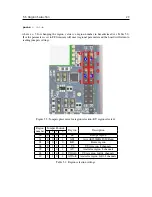
0R jumper connects P3_4 of SoM module to PS_EN, a enable signal of the low power 3.3V
converter
0R jumper selectin the source of VDD_RFS (the radio frontend power). The 0R connected on
the left side connects the VDD_RFS to low power 3.3V converter, jumper soldered on the right
side connects VDD_RFS to the V3P3_LDO (the output of internal LDO of the SoM)
2.2M Ohm resistor connected in the upper position pulls the enable line of the low power 3.3V
converter low, in the lower position pulls this line up
test point connected to the interrupt line of the temperature sensor (PTC_OS)
test point connected to the power good pin of low power 3.3V converter
test point connected to the CNTRL pin of low power 3.3V converter, pulling it high enables the
internal LDO
test point connected to the LOAD pin of low power 3.3V converter, it is a output of internal
LDO
test point connected to the SIM_MDM_LOG pin of the SIM7000E module
test point connected to the SIM_BOOT_CFG pin of the SIM7000E module
0R jumpers connect P2_3 and P3_3 GPS_UART_RXD and GPS_UART_TXD, they need to be
removed when SIM7000 is to be used

