18
Chapter 3. Hardware Architecture - Evaluation Board
Pin
Name
Function
Description
1
P2_3
UART_SIM_RX
UART interface to SIMCom module, connected with J109 jumper
2
P1_3
UART_SIM_TX
UART interface to SIMCom module, connected with J105 jumper
3
P4_3
I2C_SCL
Main I2C bus, connected with J104 jumper
4
P4_2
I2C_SDA
Main I2C bus, connected with J108 jumper
5
P1_4
-
Not used
6
P1_6
-
Not used
7
P0_7
-
Not used
8
P3_3
-
Not used
9
P3_4
PS_EN
controls enable pin of TPS62740
10
P3_2
USR_BUTTON
User button connection
11
V3P3
3.3V
3.3V power, the source selectable by J402 jumper
12
GND
GND
Ground
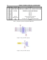
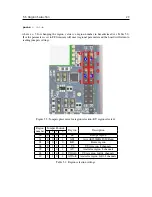
Table 3.1: Functions assignment of the MatchX SoM GPIOs
Figure 3.5: Pin-out of J102 connector.
Figure 3.6: Pin-out of J301 connector.

