7
§5 Maintenance
5.1 Cutting Torch Maintenance
Plasma cutting torches use ionized air (plasma) as the arc that “melts” the metal and is pushed away by
the compressed air. This
plasma arc exceeds 50,000°F (28,000°C)
when it is pushed through
the .030”-.040” (0.8-1.0mm) hole in the berylium copper cutting tip. Considering these extreme temperatures,
it is easy to understand the
need to replace tips & electrodes, as they become worn
, and to check that all
cooling air ports are clear to allow maximum air flow.
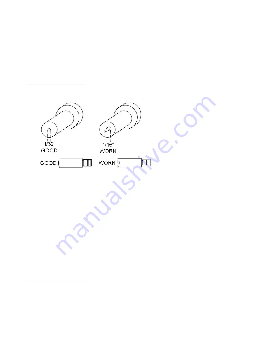
Changing Tip & Electrodes: When reduced cutting performance is observed by the operator, worn tips and
electrodes must be replaced. A simple visual inspection will determine need for replacement.
To replace tips & electrode, complete the following steps:
1) Turn power switch to OFF position, making certain power pilot LED on panel is OFF (wait 5 secs.)
2) Move torch head to clean work benchtop area and, with tip pointing up, remove shield cap.
3) Remove cutting tip and swirl ring by lifting off electrode and place both on bench.
4) Locate electrode wrench and remove electrode by rotating counter-clockwise (RH thread).
5) Inspect torch head for clogged air ports or damage.
6) Replace elctrode with new part and
tighten with wrench
. It is important to secure with wrench as
electrode transfers very high DC current at vert high temperatures.
A loose electrode will damage
the torch head
.
7) Inspect the swirl ring for any damage and replace if necessary.
8) Install the new cutting tip making sure to align with the step in the swirl ring.
9) Inspect the shield cap, making certain no melted outer covering is blocking cooling air ports. If shield
cap is burned or cover is melted, replace.
10) Reinstall shield cap, making certain it is securely turned down to the base making contact with
safety pins located in handle.
Inspecting Cables & Hoses: Upon completing torch consumable replacement, check all power cables,
hoses and the regulator glass bowl (empty water if necessary) to make certain there is no damage. In the
event of damaged insualtion on a cable, repair with proper electrical tape or shrink tubing or repalce with
new assembly.
Summary of Contents for MA48
Page 12: ...5 4 Electrical principle drawing ...
Page 13: ...5 5 PCA48 Parts Drawing ...


