24
MAXIMUS2.0
User's Manual
No. Name
Description
1
Data receiving indicator Indicator (green) for receiving data
from main unit.
2
Data sending indicator
Indicator (green) for sending data to
main unit.
3
Power indicator
I t k e e p s s t e a d y o n ( r e d ) a f t e r
Sensorbox is powered on.
4
B type USB port
Connect to main unit with USB cable
when it is applied as separated USB
device.
5
Power connector
Connect to power supply through the
power adaptor.
6
COM
Common terminal of multimeter
7
V
Ω
Hz
Testing terminal of multimeter
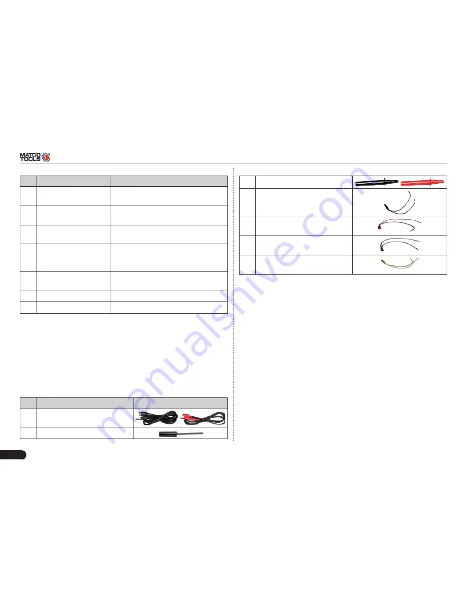
6.2.2 Sensorbox accessories
MAXIMUS2.0 sensorbox accessories include sensor test cable, probe
etc. See Table 6-2.
As the product con
fi
guration can be different, the accessories included
with the product may differ from the accessories listed on this manual.
Please see the packing list attached to the product for the detailed
accessories.
Table 2-2 Accessory checklist
No. Name
Picture
1
Sensor test cable
2
Sensor probe
3
Multimeter probe
4
Electronic control converting
cable 1
5
Electronic control converting
cable 2
6
Electronic control converting
cable 3
7
Electronic control converting
cable 4
6.3 Sensor Simulation
6.3.1 Connections
Firstly, power on the main unit (Connect one end of the power
1.
adaptor into the power interface of MAXIMUS2.0 main unit, and the
other end to the AC 220V outlet.);
Plug one end of the sensor test cable (black) into the “COM”
2.
interface of the sensorbox, then connect the other end to the test
probe or electronic control converting cable;
Connect one end of the sensor test cable (red) into the “V
Ω
Hz”
3.
interface of the sensorbox, and then connect the other end to the
test probe or electronic control converting cable.
Note: Choose corresponding cables and test probes according to
different terminals.
6.3.2 Simulation test
Simulation test enables users to exactly judge if the sensor is good or
not to avoid replacing components blindly. For example, the trouble


