MLPJ35TRF 3
04/09/18
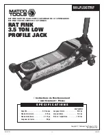
MLPJ35TRF Rat Fink 3.5 Ton Low Profile Jack
SETUP
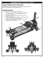
Please refer to the exploded view drawing on page 6 in this manual in
order to identify parts:
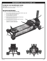
1. Remove the 2-piece handle from box. Insert narrow portion of top
section (#26) into bottom section (#28) and secure with handle
button (#27).
2. Grease the inside of the handle yoke (#24) and remove the
handle set screw (#23) from the handle yoke (#24). Insert the
handle all the way in the handle yoke (#24) until it engages the
universal joint assembly (#29). Secure the handle to the handle
yoke (#24) with the handle set screw (#23).
3. Air may become trapped in the hydraulic system during shipping
and handling. Trapped air will affect the pumping performance
of the jack. Pump the handle from its vertical position to its
horizontal position to raise the lift arm. It should take 4 to 4-1/4
full pumps for the MLPJ35TRF to reach maximum height without
a load. If the jack does not go to maximum height without a load
in the number of required strokes, follow the instructions below:
a) Rotate the handle in a clockwise direction until tight. Rotate
the handle in a counterclockwise direction two complete
revolutions.
b) Pump the handle approximately 10-15 complete pump
strokes.
c) Rotate the handle in a clockwise direction until tight. Proceed
to pump the jack to maximum lift height.
d) Repeat steps “a” through “c” until all air has been purged
from the sytem.
OPERATION
This is the safety alert symbol used for the OPERATING
INSTRUCTIONS section of this manual to alert you to
potential personal injury hazards. Obey all instructions to
avoid possible injury or death.
IMPORTANT:
Before
attempting to raise any vehicle, check vehicle service
manual for recommended lifting surfaces.
OPERATION:
1.
To raise load:
Turn the handle in a clockwise direction until tight.
Position the jack under the load. Proceed to pump the handle in
order to raise the lift arm to the load. As the saddle at the end of the
lift arm gets closer to the load, reposition the jack so the saddle will
contact the load firmly and the load is centered on the saddle. Make
sure the saddle is correctly positioned. Raise the load to the desired
work height. Place jack stands of appropriate capacity at the vehicle
manufacturers's recommended support areas that provide stable
support for the raised vehicle.
DO NOT CRAWL UNDER VEHICLE
WHILE LIFTING VEHICLE OR PLACING OR REMOVING THE JACK
STANDS!
Once jack stands are positioned, turn the handle VERY
SLOWLY in a counterclockwise direction. Lower the load to rest on
the jack stands. Inspect the relationship between the jack stands
and load to make sure the setup is stable and safe. If the setup is
not stable or safe, follow the preceding steps until corrected.
2.
To lower load:
Follow the procedures mentioned in "To raise load"
section of the OPERATING INSTRUCTIONS in order to raise the
load off the jack stands. Once the load has cleared the jack stands,
remove the stands from under the load and away from the work
area. Turn handle very slowly in a counterclockwise direction until
the load is completely lowered to the ground. Once the jack's
lifting saddle has cleared the load, remove the jack from under the
load.
DO NOT CRAWL UNDER VEHICLE WHILE LIFTING VEHICLE
OR PLACING OR REMOVING THE JACK STANDS!
CAUTION: Keep hands and feet away from the hinge mechanism of
the jack.
OWNER/USER RESPONSIBILITY
The owner and/or user must have an understanding of the
manufacturer’s operating instructions and warnings before using this
jack. Personnel involved in the use and operation of equipment shall
be careful, competent, trained, and qualified in the safe operation of
the equipment and its proper use when servicing motor vehicles and
their components. Warning information should be emphasized and
understood. If the operator is not fluent in English, the manufacturer’s
instructions and warning shall be read to and discussed with the
operator in the operator’s native language by the purchaser/owner,
making sure that the operator comprehends its contents. Owner
and/or user must study and maintain for future reference the
manufacturers’ instructions. Owner and/or user is responsible for
keeping all warning labels and instruction manuals legible and intact.
Replacement labels and literature are available from the manufacturer.
INSPECTION
Visual inspection should be made before each use of the jack,
checking for leaking hydraulic fluid and damaged, loose or missing
parts. Each jack must be inspected by a manufacturer’s repair
facility immediately if subjected to an abnormal load or shock. Any
jack which appears to be damaged in any way, is found to be badly
worn, or operates abnormally MUST BE REMOVED FROM SERVICE
until necessary repairs are made by a manufacturer’s authorized
repair facility. It is recommended that an annual inspection of the
jack be made by a manufacturer’s authorized repair facility and
that any defective parts, decals or warning labels be replaced with
manufacturer’s specified parts. A list of authorized repair facilities is
available from the manufacturer.
PROPER STORAGE
It is recommended that the jack be stored in a dry location with all
wheels touching the ground on a relatively level surface.


