Rev.
Descrizione
Redatto/Gestito
Approvato
Cod.Ident.
Pagine
Data Em.
0.6
Manuale Istruzioni
GN
UTEC
B041.M01.EN
12
/47
07/2014
5.02
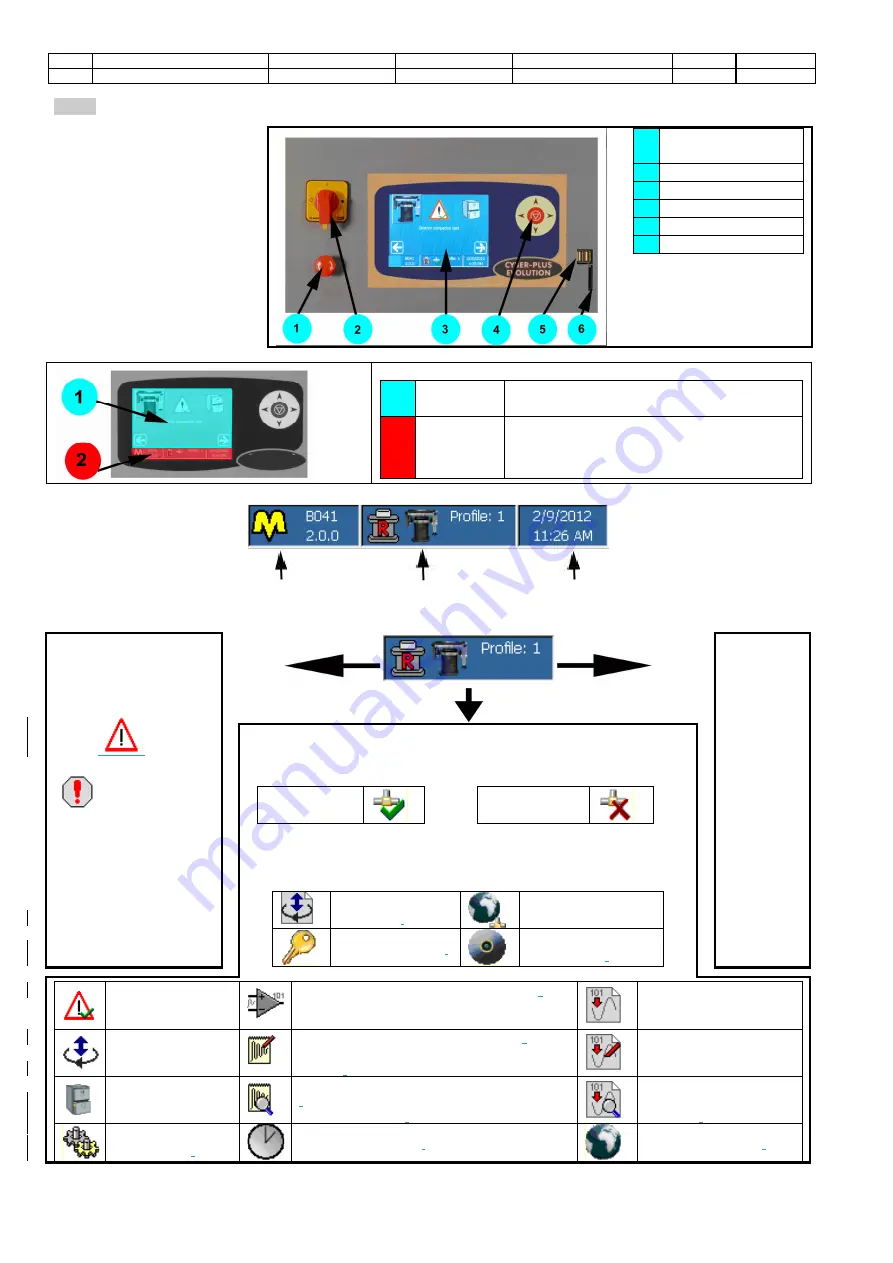
COMMANDS AND SIGNALS
The man-machine interface pass
through the LCD TFT QVGA
(320x240 pixel) touch-screen
supported by a keyboard with 5
crosswise keys.All the machine
operating
functions
are
accessible through the touch-
screen and the keyboard as well.
Depending
on
the
specific
contest the machine is working
in, some keys/functions can be
disabled or may assume a
particular meaning.
1
EMERGENCY
STOP BUTTON
2
MAIN SWITCH
3
DISPLAY
4
Keyboard
5
N°2 USB -Host
6
SLOT SD CARD
Consult the chapter related
to the screen you are
interested in to check the
exact use of the keyboard.
STRUCTURE OF THE SCREENS
1
Operating
area
It is the most important area of each screen
and it takes up the almost part of the display.
2
Status
Bar
It is divided into three parts and is placed in the
lower part of all screens. It provides with a
summary of the information concerning the
machine configuration and functioning.
Status Bar
Name and version of the machine
Status of the machine
Date and time
The central part is divided into four parts to highlight the following information:
Status of the machine
Alarm enabled or status
of the machine
It shows the presence
of one or more alarm
status
(
)
,or
configuration failure
(
) or the
operation status of the
machine
(following pages)
Configuration
profile
selected
State enabling legislation or active screen
State enabling legislation:
indicates whether the remote
execution is:
Enabled
disable
Screen enabled
:
It is represented by one of the following icons/pictures
to show the screen the operator is entering to. The list does not include
the icons that represent the Standards (see the relevant chapters). Some
screens can be entered only when using some specific machines
machine
calibration
.
network
configuration.
password change
.
software
maintenance
.
visualization of the
enabled alarms.
configuration of the input analog channel
(
the
icon also shows the number of the selected
channel).
configuration of the output
analog channel.
manual positioning.
calibration of the input analog channel
(
the icon
also shows the number of the selected
channel)
.
calibration of the output
analog channel.
test archive
check of the input analog channel calibration
(
the icon also shows the number of the
selected channel)
.
check of the output
analog channel
calibration
.
machine
configuration
.
date and time set up
.
International settings
.


